Flying needle test machine correction method

The technology of a flying probe testing machine and a calibration method, which is applied in the field of needle calibration, can solve the problems of mismeasurement, affecting the accuracy of the probe needle, and failing to tie the test point.

Active Publication Date: 2016-07-20
HANS CNC SCI & TECH
View PDF7 Cites 19 Cited by
  • Summary
  • Abstract
  • Description
  • Claims
  • Application Information

AI Technical Summary

Problems solved by technology

[0004] Before the actual test of the flying probe testing machine, the test software first needs to select two alignment points on the front and back, and then the cross target of the CCD camera under each probe needs to be aligned with the center of the alignment point, but the CCD camera and the probe There is a certain position offset. Although there

Method used


Image

  • Flying needle test machine correction method
  • Flying needle test machine correction method

Examples


Embodiment Construction

[0015] The invention provides an error correction method for a flying probe testing machine. The flying probe testing machine is equipped with a motor-driven probe on the X-Y axis that can move quickly and independently, and uses the controllable movement of the probe in the Z direction and is fixed on the machine. A device that makes contact with copper-plated holes on a PCB board and performs electrical measurements.

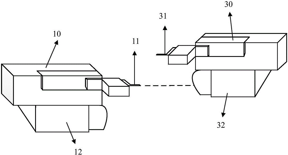
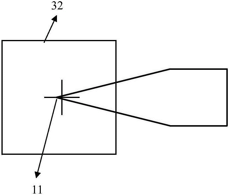
[0016] like figure 1 Shown is a schematic diagram of the local structure of the flying probe tester. The flying probe tester is provided with four test axes, namely: the first test axis 10, the second test axis (not shown), the third test axis 30, and The fourth test axis (not shown), wherein the first test axis 10 is provided with a first probe 11 and a first CCD camera 12, and the first CCD camera 12 is used to photograph the first probe on the first test axis 10 11 motion path and coordinates of the alignment point on the PCB board to be tested (printed ci...


PUM


Abstract

The present invention provides a flying needle test machine correction method. The flying needle test machine comprises a first test shaft, a second test shaft, a third test shaft and a fourth test shaft. Each test shaft is provided with one probe and one CCD camera corresponding to the probe, and the offset between the point of each probe and the center of each corresponding CCD camera and the total stroke between the probe at the right side and the probe at the inverse side in the X direction are calculated according to the correction method. According to the correction method, the offset between the point of each probe and the center of each corresponding CCD camera and the total stroke between the probe at the right side and the probe at the inverse side in the X direction are calculated are rapidly and accurately obtained. The flying needle test machine correction method employs simple and effective steps and realizes the rapid needle correction of test shafts in the condition of ensuring the correction precision of the needle.

Description

technical field [0001] The invention relates to a needle alignment calibration method for printed circuit board (PCB) testing equipment, in particular to a calibration method for a flying probe testing machine. Background technique [0002] The multi-axis flying probe testing machine is composed of four completely independent moving test needles. Under the control of the software, it moves three-dimensionally on both sides of the PCB board to be tested (2 probes on the front and 2 probes on the back) and touches the point to be tested. The electric test board applies a certain voltage and current to the test needle to obtain different test signals, so as to judge the on-off status of the PCB network to be tested. [0003] The flying probe tester (test probe) requires the test axis to have the characteristics of high speed, high precision and wide test range during the test process. The test accuracy of the flying probe tester mainly depends on the accuracy of the alignment....

Claims


Application Information

Patent Timeline
IPC IPC(8): G01R31/28
CPCG01R31/2801
Inventor 欧阳云轩张恂谢强王星翟学涛杨朝辉高云峰
Owner HANS CNC SCI & TECH
Why Eureka
Try Eureka