Tubular coil coupler structure

A coupler and tube-type technology, applied in the field of tube-type coil coupler structure, can solve the problems of low coupling efficiency and poor heat dissipation, and achieve the effects of reasonable distribution of magnetic force lines, fast heat dissipation, and low coupling frequency

Inactive Publication Date: 2016-07-20
陈奋策
View PDF7 Cites 0 Cited by
  • Summary
  • Abstract
  • Description
  • Claims
  • Application Information

AI Technical Summary

Problems solved by technology

The traditional electrodeless lamp has the following disadvantages: ...

Method used


Image

  • Tubular coil coupler structure
  • Tubular coil coupler structure
  • Tubular coil coupler structure

Examples


Embodiment 1

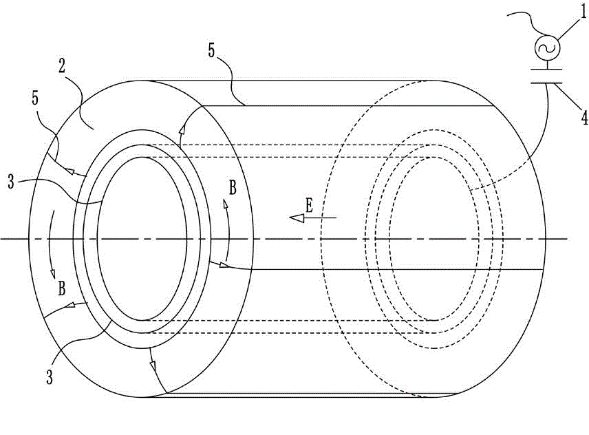
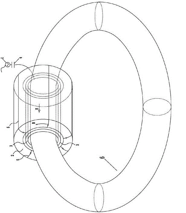
[0030] Such as figure 1 and figure 2 Shown is a schematic diagram of an embodiment of an external tubular coil coupler provided by the present invention, which includes an alternating power source 1, a hollow annular ferromagnetic core 2, a tubular metal ring group, several capacitive elements 4, a screw Winding coil 5; the hollow annular ferromagnetic core 2 is sheathed on the outer periphery of the tubular eyelet group. Such as figure 1 As shown, the spirally wound coil 5 is a coil structure in which a spirally wound wire is repeatedly wound inside and outside the side wall of the hollow annular ferromagnetic core 2, as shown in Figure 4 As shown, if the entire helical coil 5 can surround the entire hollow annular ferromagnetic core 2 to form a densely wound helical coil, the electromagnetic field will be more uniform, so that electrons can be evenly accelerated.

[0031] Such as figure 1 and 3 As shown, the tubular eyelet set includes more than one tubular eyelet A3;...

Embodiment 2

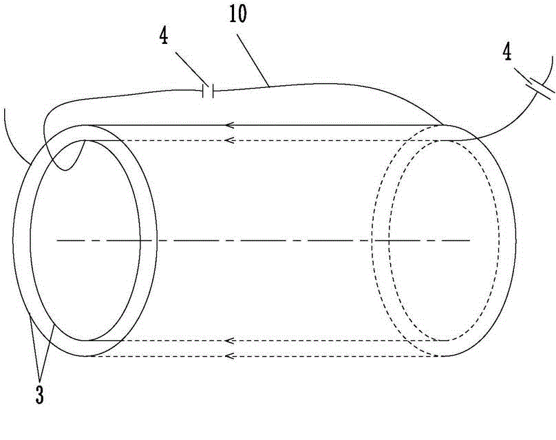
[0040] Such as Figure 10 Shown is a schematic diagram of an embodiment of a built-in tubular coil coupler provided by the present invention, which includes an alternating power source 1, a hollow annular ferromagnetic core 2, a tubular metal ring group, several capacitors 4, a screw Wound coil 5; the tubular metal ring set is sleeved on the outer periphery of the hollow annular ferromagnetic core 2, and the spiral wound coil 5 is a spiral wound wire repeatedly wound along the outer wall surface of the hollow annular ferromagnetic core 2 A plurality of wire loops are formed, and the plurality of wire loops are uniformly distributed from one end to the other end of the hollow annular ferromagnetic core 2 in sequence. Preferably, a plurality of wire loops are gradually arranged from one end of the hollow annular ferromagnetic core to the other end to form a densely wound spiral coil structure, which can ensure that the electromagnetic field around the hollow annular ferromagneti...


PUM


Abstract

The invention relates to a tubular coil coupler structure, relates to equipment, relating to power coupling, of a tubular coil-coupled electrodeless lamp and the like, and aims at providing a tubular coil coupler which is high in coupling efficiency, low in coupling frequency, reasonable in effective magnetic line distribution, high in heat dissipation rate, high in magnetic flux and energy-saving. The tubular coil coupler comprises an alternating power source, a hollow annular ferromagnetic core, a tubular metal coil group, a plurality of capacitor parts and a solenoidal coil. Compared with the prior art, the tubular coil coupler has the advantages that a new coupler is added for an existing power coupler; the tubular coil coupler is high in coupling efficiency, low in coupling frequency, reasonable in effective magnetic line distribution, high in heat dissipation rate, high in magnetic flux and energy-saving; the hollow annular ferromagnetic core is directly connected with air, and is high in heat dissipation rate; and a tubular coil of the built-in coupler plays auxiliary heat dissipation and support roles.

Description

technical field [0001] The invention relates to a tubular coil coupler structure, which is applied to equipment involving power coupling such as tubular coil coupling electrodeless lamps. Background technique [0002] Tubular coil power coupler is a high-tech product developed by integrating the latest scientific and technological achievements in the fields of power electronics, plasma science, dielectric and magnetic materials, and has broad applications in occasions involving power coupling. One example of the application of tubular coil power coupler, such as electrodeless lamps. The electrodeless lamp has no filament and no electrode, which is the abbreviation of electrodeless gas discharge fluorescent lamp. Electrodeless lamp is a new light source with high light efficiency, long life and high color rendering. Existing electrodeless lamps are divided into two types: the hollow annular ferromagnetic core external type and the ferromagnetic core internal type, includi...

Claims


Application Information

Patent Timeline
IPC IPC(8): H01J65/04
Inventor 陈奋策陈苏
Owner 陈奋策
Why Eureka
Try Eureka