U-shaped groove based UWB band-pass filter

A band-pass filter, U-shaped slot technology, applied in waveguide-type devices, electrical components, circuits, etc., to achieve the effect of simple design, compact structure and convenient processing

Inactive Publication Date: 2016-07-20
HARBIN HESON SCI & TECH
View PDF0 Cites 0 Cited by
  • Summary
  • Abstract
  • Description
  • Claims
  • Application Information

AI Technical Summary

Problems solved by technology

At the same time, it also poses more challenges to us, because most of the existing communication syst

Method used


Image

  • U-shaped groove based UWB band-pass filter
  • U-shaped groove based UWB band-pass filter

Examples


Embodiment Construction

[0018] The invention designs a UWB band-pass filter based on a U-shaped groove, and the filter has a wider pass band, smaller return loss and insertion loss, and good out-of-band characteristics.

[0019] The invention will be described in more detail below in conjunction with the accompanying drawings:

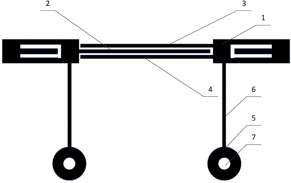
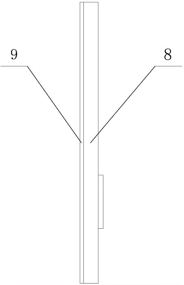
[0020] An example of the present invention is figure 1 As shown, the dielectric substrate (8) is FR-4 with a dielectric constant of 4.9. The dielectric substrate has a thickness of 1 mm. The grounding plate (9) under the dielectric substrate is made of copper material.

[0021] Such as figure 1 As shown, the present invention is a UWB bandpass filter based on U-shaped slots, the open circuit stub structures (1), (2), and the microstrip structure (5) of 50 ohm stubs on the dielectric substrate are made of copper material.

[0022] The design parameters of a UWB bandpass filter based on the U-shaped groove of the invention:

[0023] Selection of dielectric substrate: FR4 m...


PUM


Abstract

The invention discloses a U-shaped groove based UWB band-pass filter. The filter comprises open circuit stub structures (1) and (2), a 50-ohm-stub microstrip structure (5) and a ground (9) on the lower surface of a dielectric plate. The filter adopts an interdigital coupling structure formed by three 50-ohm transmission microstrip lines to realize the ultra wide band. The filter provided by the invention has low return loss and insertion loss, a good high low-frequency characteristic and high harmonic rejection capability; and meanwhile, the filter is simple in design, compact in structure, attractive in appearance, convenient to process, low in cost, and capable of realizing the 3.1-10.6GHz ultra wide band.

Description

technical field [0001] The invention relates to a UWB band-pass filter based on a U-shaped slot, which can realize ultra-wideband in the 3.1-10.6GHz frequency band. Background technique [0002] UWB technology appeared in the late 1950s and was mainly used in military radars and communication systems with low intercept rates until the 1990s. In recent years, with the development of microelectronic device technology and technology, UWB technology has only begun to be gradually applied in the civilian field. On February 14, 2002, ultra-wideband wireless technology was first approved by the FCC of the Federal Communications Commission of the United States and can be used in short-distance wireless communications. This opened the door for the commercial application of ultra-wideband technology products and promoted ultra-wideband systems and Its devices such as: UWB filter, UWB antenna, UWB amplifier and other research progress. [0003] UWB technology can be applied in a wide...

Claims


Application Information

Patent Timeline
IPC IPC(8): H01P1/212
Inventor 郝术苗孙照清赵永生
Owner HARBIN HESON SCI & TECH
Why Eureka
Try Eureka