
Light field imaging device and parameter determination method thereof

A light field imaging and imaging technology, applied in optics, image communication, television, etc., can solve problems such as complex manufacturing process, unfavorable high-resolution imaging, clear imaging, etc., to achieve increased dynamic range, wide application prospects, and dynamic range big effect

Active Publication Date: 2016-07-20
NAT UNIV OF DEFENSE TECH
View PDF3 Cites 17 Cited by
  • Summary
  • Abstract
  • Description
  • Claims
  • Application Information

AI Technical Summary

Problems solved by technology

[0003] However, due to the principle that the measurement accuracy of the spatial coordinate information and the direction information of the light field are mutually inhibited, the vertical depth extraction accuracy and the horizontal imaging resolution of the traditional light field camera cannot be improved at the same time. there are certain limitations
Although the first-generation light field camera can capture and image the target in multiple viewing angles, it has certain advantages in the acquisition of scene object depth and complex aberration detection, but it wastes a lot of lateral imaging resolution, which is used for imaging. Effective pixels only occupy a small part of the pixels, which is not conducive to high-resolution imaging
The second-generation light field camera can restore the depth information of the scene object by using the acquired imaging information of a part of the angle of view in accordance with the principle of parallax when only the defocus item caused by the distance is considered, which effectively improves the spatial resolution of the imaging, but its The dynamic range of measuring the depth of the measured object is also greatly reduced
When the existing second-generation focused light field cameras and various types of light field acquisition structures obtain light field information, when using traditional light field cameras to image targets, the light field cameras with a single structure can only capture objects within a certain depth of field. The light field information in the object space is imaged and recorded, and the depth extraction range is limited. Often, objects outside the design depth of field of the light field camera cannot be clearly imaged, and then the depth extraction function is lost. Therefore, it is necessary to rely on the synchronization of multiple light field cameras with different parameters. Only by obtaining light field information in various depth ranges can clear imaging and depth extraction of objects in a large depth of field be possible.
For example, Raytrix Company draws on previous design experience to design microlenses with different parameters on the same template for manufacturing, and integrate light field cameras with different parameters into the same device to increase the depth measurement of scene objects. dynamic range, but its manufacturing process is complicated, the composite microlens array is expensive, and its application is limited to scientific research

Method used


Image

  • Light field imaging device and parameter determination method thereof
  • Light field imaging device and parameter determination method thereof
  • Light field imaging device and parameter determination method thereof

Examples


Embodiment Construction

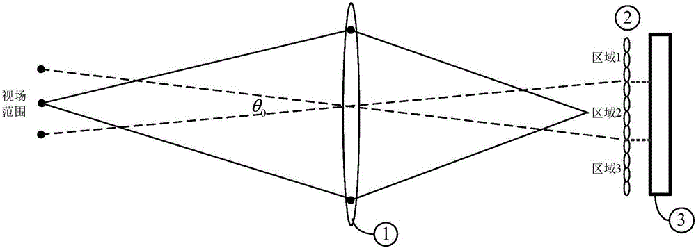
[0056] like figure 1 , figure 2 , image 3 and Figure 4 As shown, the light field imaging device of this embodiment includes an imaging main lens 1, a microlens array 2, and a photosensitive CCD 3 for imaging information collection arranged in parallel in sequence. The microlens array 2 includes a plurality of microlenses arranged on the same plane, and the microlens array 2 is divided into multiple imaging acquisition sub-areas for acquiring light field information in different depth ranges, and the entrance pupil surface side of the main imaging lens 1 is closely connected with orthogonal The defocusing grating 4, the orthogonal defocusing grating 4 includes two Fresnel zone plates arranged in parallel, the Fresnel zone plates are off-axis (the zone center of the Fresnel zone plate does not coincide with the geometric center) The amplitude type Fresnel zone plate or the phase type Fresnel zone plate. see Figure 4 , the orthogonal defocus grating 4 of this embodiment ...


PUM


Abstract

The invention discloses a light field imaging device and a parameter determination method thereof. The light field imaging device comprises an imaging main lens, a microlens array and an imaging information acquisition photosensitive CCD, which are arranged in parallel in sequence. The microlens array comprises a plurality of microlenses arranged in the same plane; and the entrance pupil surface side of the imaging main lens is closely connected with orthogonal defocus gratings for imaging light field information in different depth ranges to different regions of the microlens array. The parameter determination method comprises the following steps: dividing the microlens array into imaging acquisition sub-regions; selecting focal length and aperture of the imaging main lens; determining system equivalent focal length of the different imaging acquisition sub-regions and off-axis magnitude of the orthogonal defocus gratings; determining stripe parameters of the orthogonal defocus gratings; and selecting parameters of the microlens array. The light field imaging device has the advantages of high imaging resolution, large depth extraction dynamic range, wide application range, simple structure and low cost.

Description

technical field [0001] The invention relates to light field imaging technology, in particular to a light field imaging device and a parameter determination method thereof. Background technique [0002] With the rapid development of imaging technology, people are no longer satisfied with imaging with high resolution and large depth of field, but are eager to obtain full optical field information including object depth information in imaging. Among the many possible all-optical-field information acquisition methods, integrated imaging is a very potential and promising three-dimensional imaging technology. With the development of the microlens array manufacturing process and the popularization of high-resolution image sensors, the performance of the integrated imaging structure using the microlens array, such as depth of field, field of view and resolution, has also been greatly improved. Due to its simple structure, easy operation, portability and low cost, the developed ligh...

Claims


Application Information

Patent Timeline
IPC IPC(8): H04N5/225H04N5/232G03B17/12
CPCG03B17/12H04N23/55H04N23/67
Inventor 许晓军吕洋马浩统张烜喆宁禹吴武明孙全杜少军司磊
Owner NAT UNIV OF DEFENSE TECH
Learn More