Thermographic inspection system

A detection system, thermal imaging technology

Inactive Publication Date: 2016-07-20
WATLOW ELECTRIC MFG
View PDF18 Cites 3 Cited by
  • Summary
  • Abstract
  • Description
  • Claims
  • Application Information

AI Technical Summary

Problems solved by technology

As a result, the heat entering the object may not be sufficient to cause an acceptable surface temperature difference that is easily visible with a thermal imaging camera
[0005...

Method used


Image

  • Thermographic inspection system
  • Thermographic inspection system
  • Thermographic inspection system

Examples


Embodiment Construction

[0016] The following description is merely exemplary in nature, and is not intended to limit the present invention, application, or use.

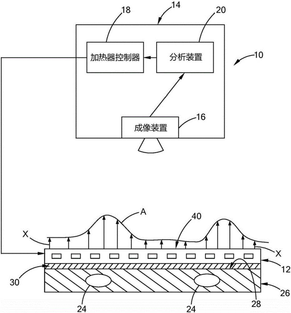
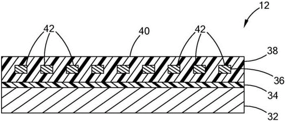
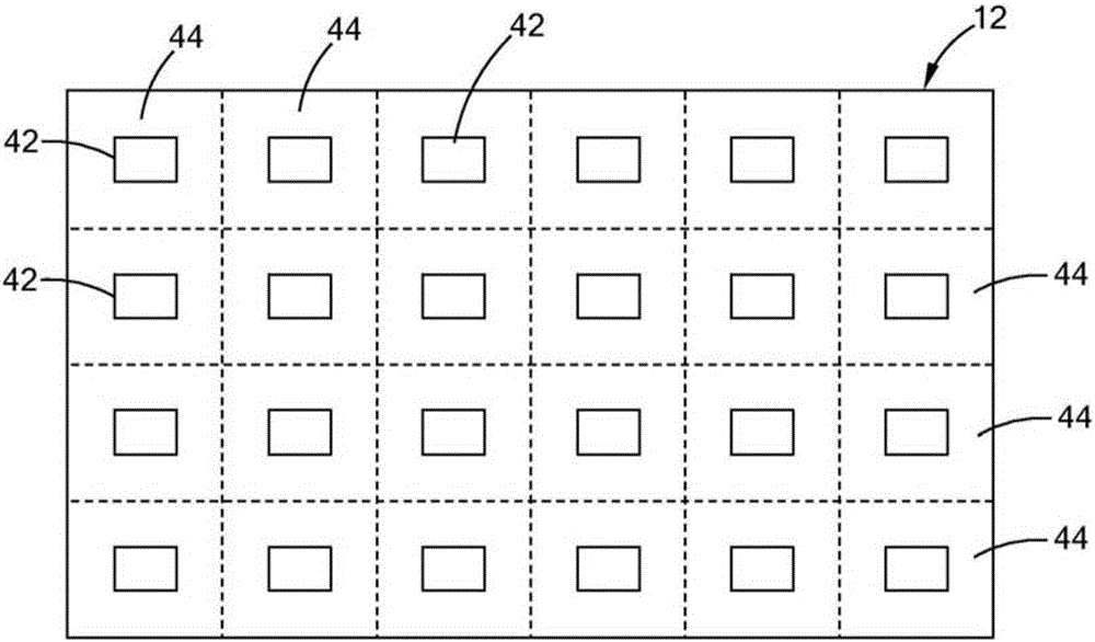
[0017] reference figure 1 The thermal imaging detection system 10 according to the teachings of the present invention includes a pixel heater 12 and a control system 14. The control system 14 includes a heater controller 16 for controlling the pixel heater 12, an imaging device 18 that acquires a thermal image of the pixel heater 12, and an analysis to determine the position of internal structures (such as defects or voids 24) in the object 26 装置20。 Device 20. The pixel heater 12 is formed as a sheet structure and is removably attached to the outer surface 28 of the object 26. The term "sheet-like" is defined herein as a plate, a generally flat sheet of material. The sheet-like structure can therefore have many overall shapes, such as rectangles, squares, circles, triangles, etc., or can be customized to fit a specific object 26. Preferably,...


PUM


Abstract

The invention discloses an infrared thermographic inspection system (10), which includes a heat source (12) configured to be removably attached to an exterior surface (28) of an object (26). A thermal imaging device (16) obtains a thermal image of the object (26), and an analyzing device (20) determines a location of a defect (24) in the object (26) based on the thermal image. The heat source (12) consists of a flexible polyimide heater (12) comprising a plurality of heating elements (42) which are independently controlled and the flexible heater can conform to the exterior surface (28) of the object (26).

Description

Technical field [0001] The present invention relates to non-destructive testing (NDT), and more specifically to thermal imaging detection systems and methods for detecting objects. Background technique [0002] The statements in this section only provide background information related to the present invention, and may not constitute prior art. [0003] Non-destructive testing (NDT) usually involves introducing external stimuli to the object to detect the object without permanently changing the material properties of the object. Thermal imaging is a non-destructive testing technique and uses an external energy source to heat the object and cause a temperature difference between defective and non-defective areas in the object. One common thermal imaging detection technique uses optical excitation, in which pulsed light from a flash lamp (such as a xenon flash lamp) is delivered to the subject. Once reaching the outer surface of the object, the light is converted into heat, which in...

Claims


Application Information

Patent Timeline
IPC IPC(8): G01N25/18G01N25/72
CPCG01N25/72G01J5/48G01N25/18H04N5/33
Inventor 穆罕默德·诺斯拉蒂卡尔·斯汪森凯文·帕塔斯恩斯基凯文·R·史密斯路易斯·P·辛德豪尔
Owner WATLOW ELECTRIC MFG
Why Eureka
Try Eureka