Shoe-washing machine

A technology of shoe washing machine and shoe rack, which is applied in the field of shoe washing machines, can solve problems such as difficult to completely remove stains, cannot thoroughly clean the inside of shoes, and requires a large water flow, etc., and achieves simple dehydration, good washing effect, and simple structure Effect

Active Publication Date: 2016-07-27
QINGDAO HAIER WASHING MASCH CO LTD +1
View PDF9 Cites 13 Cited by
  • Summary
  • Abstract
  • Description
  • Claims
  • Application Information

AI Technical Summary

Problems solved by technology

[0007] The above invention patent discloses a method and device for cleaning shoes by adding friction balls into the water flow and driving the friction balls through the water flow. After actual verification, it is found that the use of this method requires a lot of water flow, and even if the water flow is sufficient, only relying on the water flow to drive the shoe. It is also difficult to completely remove the stains on the shoes with friction ball cleaning, and due to the existence of the upper, the friction balls entering the inside of the shoes are no longer driven by a large water flow, resulting in the inability to thoroughly clean the inside of the shoes

Method used


Image

  • Shoe-washing machine
  • Shoe-washing machine
  • Shoe-washing machine

Examples


Embodiment 1

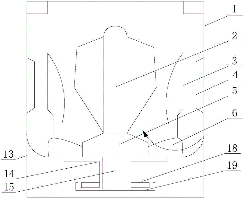
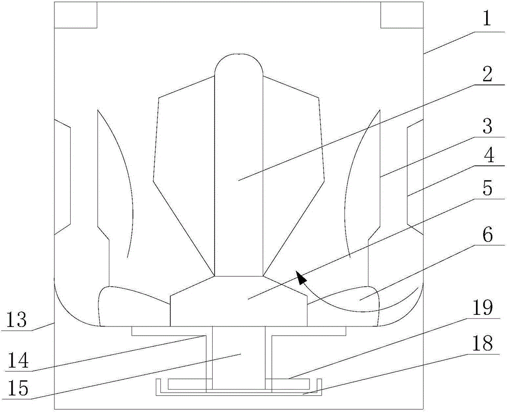
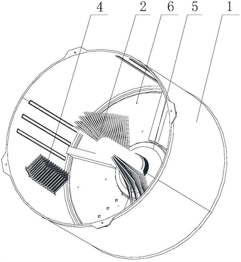
[0050] like figure 1 , figure 2 , Figure 4 and Figure 5 As shown, the shoe washing machine of this embodiment includes a water tub 1 and an inner pulsator 5 and an outer pulsator 6 respectively arranged inside the water tub 1 , and the inner pulsator 5 is fixedly arranged at the bottom central position of the water tub 1 The outer pulsator 6 is rotatably arranged on the periphery of the inner pulsator 5; the inner pulsator 5 is provided with a central brush 2, and the inner wall of the water bucket 1 is provided with a bucket wall brush 4.

[0051] In order to further improve the washing effect of the shoe washing machine of the present invention on the shoes, the outer pulsator 6 of the present invention is detachably installed with a shoe rack 3 for placing shoes, and the shoe rack 3 and the outer pulsator 6 rotate integrally. The shoe rack 3 of the present invention is mainly used to support and place shoes, so that the shoes are better subjected to the friction of th...

Embodiment 2

[0060] The shoe washing machine of this embodiment includes a water tub 1 and an inner pulsator 5 and an outer pulsator 6 respectively arranged inside the water tub 1. The pulsator 6 is rotatably arranged on the periphery of the inner pulsator 5; the inner pulsator 5 is provided with a central brush 2, and the inner wall of the water bucket 1 is provided with a bucket wall brush 4.

[0061] like Figure 8 As shown, the central brush 2 of this implementation is detachably installed on the inner pulsator 5, and the disassembly and installation method mainly has the following advantages:

[0062] (1) In the washing state, the central brush 2 is mounted on the inner pulsator 5; in the dehydration state, the central brush 2 is disassembled from the inner pulsator 5.

[0063] The central hairbrush is pulled down during dehydration like this, prevents that in the dehydration process, the central hairbrush 5 causes damage to shoes.

[0064] (2) When washing items other than shoes, s...

Embodiment 3

[0072] The shoe washing machine of this embodiment includes a water tub 1 and an inner pulsator 5 and an outer pulsator 6 respectively arranged inside the water tub 1. The pulsator 6 is rotatably arranged on the periphery of the inner pulsator 5; the inner pulsator 5 is provided with a central brush 2, and the inner wall of the water bucket 1 is provided with a bucket wall brush 4.

[0073] The central hairbrush 2 of this embodiment comprises cylinder 201 and central bristle 202, as Image 6 As shown, the central bristles 202 are arranged on the cylinder 201 in a spiral shape, so that the central bristles 202 can better contact with the upper of the shoes on the shoe rack 3, and the cleaning effect of the central bristles 202 can be improved. like Figure 7 As shown, the central bristles 202 are set up big and down, so that the central bristles 202 are in better contact with the upper of the shoe, and the cleaning effect of the central bristles 202 is improved.


PUM


Abstract

The invention provides a shoe-washing machine. The shoe-washing machine comprises a water-containing barrel, as well as an inner impeller and an outer impeller which are arranged inside the water-containing barrel, wherein the inner impeller is fixedly arranged in the central position of the bottom of the water-containing barrel, and the outer impeller is rotatably arranged on the periphery of the inner impeller; a central hairbrush is arranged on the inner impeller, and a barrel wall hairbrush is arranged on the inner wall of the water-containing barrel. According to the shoe-washing machine, two impellers, namely, the inner impeller and the outer impeller are arranged inside the water-containing barrel, the inner impeller is fixedly arranged in the central position of the bottom of the water-containing barrel, the outer impeller is rotatably arranged on the periphery of the inner impeller, the central hairbrush is arranged on the inner impeller, and the barrel wall hairbrush is arranged on the inner wall of the water-containing barrel. In the washing state, the outer impeller rotates to drive shoes to move, in the moving process of the shoes, the shoes have contact friction with the fixed central hairbrush so as to be washed, and meanwhile, the barrel wall hairbrush can rub the other sides of the shoes, so that the washing effect is further improved.

Description

technical field [0001] The invention relates to the technical field of shoe washing equipment, in particular to a shoe washing machine. Background technique [0002] Washing machine, as a kind of commonly used household appliances, effectively solves the requirements of people for washing clothes in daily life, but there is no effective solution for washing shoes. If directly wash shoes with existing shoe washing machine, there will be following disadvantages: [0003] First of all, the traditional washing machine is used to wash shoes, because the washing machine mainly uses water flow to agitate clothes for washing, and due to the structural characteristics of shoes, the cleanliness of shoes cannot be guaranteed. [0004] Secondly, because the washing machine consumes a lot of water, when the number of shoes to be washed is small, using a washing machine to wash will waste a large amount of water resources. [0005] Finally, because the shoes contain more bacteria, and s...

Claims


Application Information

Patent Timeline
Patent Type & Authority Applications(China)
IPC IPC(8): A47L23/02
Inventor 陈维会刘杰王佑喜傅燕敏徐鹏飞张萌
Owner QINGDAO HAIER WASHING MASCH CO LTD
Why Eureka
Try Eureka