Tail end swinging joint driving mechanism

A driving mechanism and joint technology, which is applied in the field of swing joint drive mechanism, can solve the problems that the slack wire cannot be instantly changed into the tension wire, the position and posture of the end swing joint are unstable, and the processing and assembly are complicated, so as to achieve precise operation and simple structure , the effect of reducing fatigue

Active Publication Date: 2016-07-27
TIANJIN UNIV
View PDF11 Cites 0 Cited by
  • Summary
  • Abstract
  • Description
  • Claims
  • Application Information

AI Technical Summary

Problems solved by technology

The driving mechanisms of the existing end swing joints are mostly ball pin pairs or Hooke hinges. The main problem of the two is that when driving the end swing joints, the displacement of the driving end of the tensioned steel wire rope and the slack steel wire rope is not equal. When swinging in the opp

Method used


Image

  • Tail end swinging joint driving mechanism
  • Tail end swinging joint driving mechanism
  • Tail end swinging joint driving mechanism

Examples


Example Embodiment

[0018] The specific embodiments of the present invention will be described in detail below with reference to the accompanying drawings.

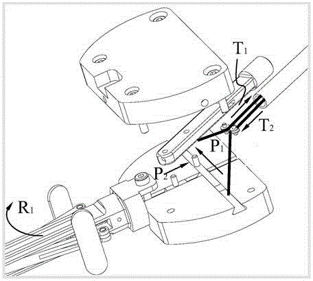
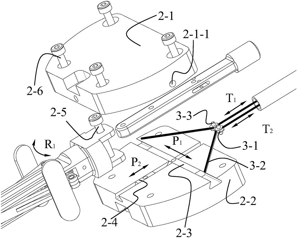
[0019] As shown in the accompanying drawings, the end swing joint drive mechanism of the present invention includes a lower bottom plate 2-2, and a horizontal dovetail guide groove 2-2- is vertically intersected along the transverse direction and the longitudinal direction on the lower bottom plate 2-2. 1 and the longitudinal dovetail guide groove 2-2-2, the transverse guide rail 2-3 is slidably connected in the said transverse dovetail guide groove 2-2-1 to realize the transverse dovetail of the transverse guide rail 2-3 on the lower bottom plate 2-2 Slide left and right in the guide groove 2-2-1. A longitudinal guide rail 2-4 is slidably connected in the longitudinal dovetail guide groove 2-2-2, so that the longitudinal guide rail 2-4 slides back and forth in the longitudinal dovetail guide groove 2-2-2 of the lower bottom plate 2-2. A first...


PUM


Abstract

The invention discloses a tail end swinging joint driving mechanism, which comprises a lower bottom plate, wherein a transverse dovetail guide groove and a longitudinal dovetail guide groove are respectively formed in the lower bottom plate; a transverse guide rail is glidingly connected in the transverse dovetail guide groove; a longitudinal guide rail is glidingly connected in the longitudinal dovetail guide groove; a first pin shaft is connected onto the transverse guide rail; a second pin shaft is connected onto the longitudinal guide rail; the first pin shaft and the second pin shaft are respectively inserted into pin holes of a tool connecting rod for forming two rotating pairs; an upper bottom plate is fixed on the lower bottom plate; a tool connecting rod moving stroke groove is formed in the bottom surface of the upper bottom plate; the back end of the tool connecting rod is arranged in the stroke groove; a steel wire rope moving stroke groove is formed in the front end of the bottom surface of the upper bottom plate; one ends of the two steel wire ropes are respectively guided by one wire guide wheel and then pass through the steel wire rope moving stroke grooves formed in the corresponding side to be fixed in the wire fixing holes of the upper bottom plate; the two wire guide wheels are respectively fixed in the tool connecting rod through wire guide wheel pin shafts. The equal extension and contraction of the tail end swinging joint can be realized.

Description

technical field [0001] The invention relates to a drive mechanism for a swing joint, in particular to a drive mechanism for a swing joint used in a minimally invasive surgical instrument, in particular to a drive mechanism for a swing joint used in single-hole surgery and natural orifice surgery. Background technique [0002] Minimally invasive surgery refers to the surgical operation performed by doctors using modern medical equipment such as abdominal and thoracoscopes and supporting equipment. The derivation of minimally invasive surgical technology has made important contributions to the promotion of human development and civilization progress, and has become a global surgical field in the 21st century. main theme. Compared with open surgery, minimally invasive surgery has many advantages such as less trauma, less bleeding, and faster recovery, and has been more and more widely used in clinical operations. In recent years, with the development of science and technology ...

Claims


Application Information

Patent Timeline
IPC IPC(8): A61B34/30A61B90/50A61B17/00
CPCA61B17/00234A61B2017/00238
Inventor 王树新马翁张国凯
Owner TIANJIN UNIV
Why Eureka
Try Eureka