Improved desulphurization device

A desulfurization equipment and wet desulfurization technology, applied in the field of machinery, can solve the problems of large area, high cost, scattered structure, etc., and achieve the effect of reducing the area, reducing the gap, and improving the compactness of the structure

Inactive Publication Date: 2016-07-27
浙江宝峰热电有限公司
View PDF5 Cites 2 Cited by
  • Summary
  • Abstract
  • Description
  • Claims
  • Application Information

AI Technical Summary

Problems solved by technology

[0004] There is a problem with the above-mentioned desulfurization equipment: there is a one-to-one correspondence between the boiler and the parts that perform the desulfurization

Method used


Image

  • Improved desulphurization device
  • Improved desulphurization device
  • Improved desulphurization device

Examples


Example Embodiment

[0024] Example one

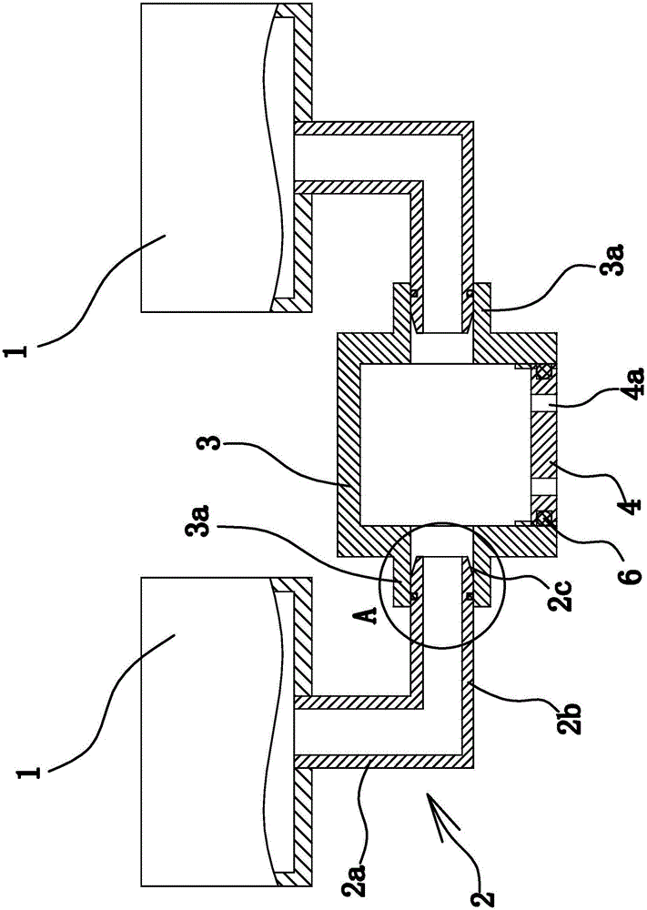
[0025] Such as figure 1 As shown, the improved desulfurization equipment is composed of a wet desulfurization device 1, a gas pipe 2, a connecting pipe 3, a connecting plate 4, and the like. Among them, the wet desulfurization device 1 is an existing product, such as a wet desulfurization device disclosed by the Chinese Patent Library [application number: 201510796580.4; publication number: CN105268304A], and the bottom of the wet desulfurization device 1 has a flue gas inlet .

[0026] Specifically, there are two wet desulfurization devices 1 arranged side by side. Each wet desulfurization device 1 is provided with an air pipe 2 at the bottom, each air pipe 2 is L-shaped, and each air pipe 2 includes a vertically arranged air outlet 2a and a horizontally arranged air inlet 2b. Among them, the two air outlets 2a are respectively connected with two flue gas inlets. In this embodiment, the upper end of the gas outlet portion 2a is inserted into the flue gas in...

Example Embodiment

[0031] Example two

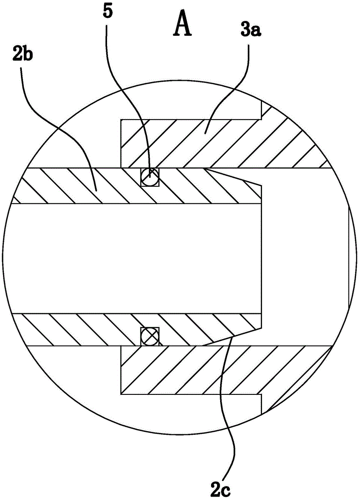
[0032] The structure and principle of the second embodiment are basically the same as those of the first embodiment. The difference lies in: the outer side wall of the air inlet portion 2b has a convex annular shoulder, and the annular shoulder is coaxial with the inlet portion 2b and has an annular shape. The shoulder and the connecting portion 3a abut against each other. The sealing structure includes an annular groove provided on the end surface of the annular shoulder and an annular sealing gasket arranged in the annular groove. The two end surfaces of the annular gasket respectively abut against the bottom wall of the annular groove and the end surface of the connecting portion 3a.


PUM


Abstract

The invention provides an improved desulphurization device, belonging to the technical field of machinery. The invention aims at solving the problem that the existing desulphurization device is scattered in structure. The improved desulphurization device comprises two wet desulphurization devices arranged side by side, and a flue gas inlet is formed in the bottom of each wet desulphurization device; an L-shaped gas pipe is arranged at the bottom of each wet desulphurization device, each gas pipe comprises a vertically arranged gas outlet part and a horizontally arranged gas inlet part, the two gas outlet parts are respectively communicated with the two flue gas inlets, and a straight pipe-shaped connecting pipe is vertically arranged between the two gas inlet parts; the gas pipes are fixed with the connecting pipe; the two gas inlet parts are respectively communicated with the connecting pipe; the upper end of the connecting pipe is closed, and an opening is formed in the lower end of the connecting pipe; the lower end of the connecting pipe is internally connected with a connecting plate in a screwing way; four through holes are formed, along the axial direction of the connecting pipe, in the connecting plate in a penetrating way; a ring-shaped groove is formed in the side wall of the connecting plate; an O-shaped sealing ring I is arranged in the ring-shaped groove, and the peripheral surface of the O-shaped sealing ring I props against the inner side wall of the connecting pipe. The improved desulphurization device has the advantage of being compact in structure.

Description

technical field [0001] The invention belongs to the technical field of machinery and relates to an improved desulfurization equipment. Background technique [0002] The boiler is a kind of energy conversion equipment. The energy input to the boiler includes chemical energy and electric energy in the fuel, and the boiler outputs steam, high-temperature water or organic heat carrier with a certain amount of heat energy. The hot water or steam generated in the boiler can directly provide the required heat energy for industrial production and people's life, and can also be converted into mechanical energy through a steam power device, or converted into electrical energy through a generator. Due to the low cost of coal combustion, most enterprises in my country still use traditional coal as boiler fuel. However, coal will produce more sulfides during the combustion process, and direct discharge will inevitably cause immeasurable pollution to the environment. Therefore, desulfur...

Claims


Application Information

Patent Timeline
IPC IPC(8): B01D53/78B01D53/48
CPCB01D53/78B01D53/48B01D2258/0283
Inventor 朱延庆杨春福
Owner 浙江宝峰热电有限公司
Why Eureka
Try Eureka