Grabbing manipulator capable of turning over box body

A technology for grasping manipulators and boxes, applied in manipulators, program-controlled manipulators, chucks, etc., to achieve the effects of high mechanical strength, expanded range and strong working stability

Inactive Publication Date: 2016-07-27
HARBIN UNIV OF SCI & TECH
View PDF5 Cites 26 Cited by
  • Summary
  • Abstract
  • Description
  • Claims
  • Application Information

AI Technical Summary

Problems solved by technology

[0003] The present invention: a gripping manipulator for reversible boxes, which mainly solves the problem of a...

Method used


Image

  • Grabbing manipulator capable of turning over box body
  • Grabbing manipulator capable of turning over box body
  • Grabbing manipulator capable of turning over box body

Examples


specific Embodiment approach 1

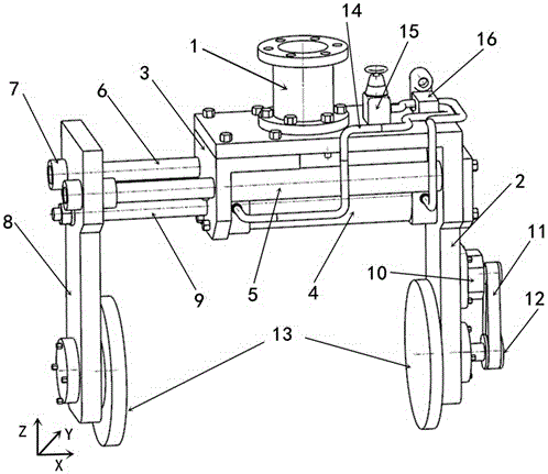
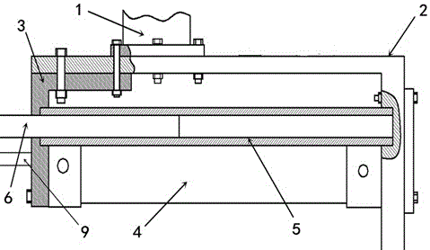
[0017] Embodiment 1: A grabbing manipulator for a reversible box is installed at the end of a rotating manipulator of a Cartesian robot. The Cartesian robot controls the manipulator to reach the specified grabbing position and grabbing angle by moving along the X-axis, Y-axis, and Z-axis and rotating around the Z-axis. The electromagnetic control reversing valve controls the air pressure rod through the air cylinder to drive the movable splint to do horizontal reciprocating movement, which can adjust the clamping width of the manipulator. The movable splint is connected with the guide rod through the sleeve, the guide rod slides in the guide sleeve, and the guide rod and the guide sleeve play the role of guide rail and support. Two pairs of guide rods and guide sleeves are parallel to each other. The sleeve is symmetrically extended and installed on the movable splint, and the sleeve and the guide rod are shrunk fit together to increase the contact area and strengthen the con...

specific Embodiment approach 2

[0019] Specific implementation mode 2: Cartesian coordinate robot controls the manipulator to move to the preset grabbing position, and the mechanical arm rotates at a certain angle, so that the gripping surfaces of the two gripping discs are in contact with the two symmetrical surfaces of the box for gripping. Cartesian coordinates The robot then adjusts the height of the manipulator, moves to the designated position and places it. The work of the pneumatic control circuit is to complete the grabbing and placing of the box body according to the specific embodiment one.

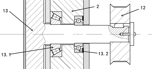
[0020] The active gripping disc is mounted on the fixed clamping plate with a tapered roller bearing and a deep groove ball bearing. The tapered roller bearing offsets the axial force generated by the clamping disc, and the deep groove ball bearing offsets the radial force generated by the clamping disc. This structure makes the structure of the manipulator more compact. The bearing is fixed with the fixed s...


PUM


Abstract

The invention provides a grabbing manipulator capable of turning over a box body. The grabbing manipulator is connected with the tail end of a rotating mechanical arm of a right-angle coordinate robot and comprises a supporting mechanism, a displacement adjusting mechanism, a clamping mechanism and a pneumatic control loop. The supporting mechanism is composed of a connecting arm, a fixed clamping plate and a fixing plate. The displacement adjusting mechanism is composed of a movable clamping plate, guide rods, guide sleeves, a pneumatic rod and a pneumatic cylinder. The clamping mechanism is composed of clamping round plates, a servo motor, a synchronous belt and a synchronous wheel. The pneumatic control loop is composed of a pneumatic hose, a direct acting pressure reducing valve and an electromagnetic control reversing valve. According to the grabbing manipulator capable of turning over the box body, the clamping force can be clamped in a whole joint mode through the pneumatic control loop so that grabbing of the heavy box body can be adapted; and the servo motor drives the synchronous wheel to rotate through the synchronous belt, the driving clamping plate can be controlled to forwards and reversely rotate by any angles, the driven clamping plate and the box body rotate along with the driving clamping plate, and hence the posture of the box body can be adjusted after the box body is grabbed by the clamping mechanism.

Description

technical field [0001] The present invention relates to a gripping manipulator for a reversible box, which relates to the technical field of automation equipment, and in particular to a manipulator based on a Cartesian robot, which can grip and hold boxes of different sizes, qualities and hardnesses. Flip it at any angle, and place it according to the specified position and posture. Background technique [0002] In the field of industrial and home appliance production, the use of robots for the handling of box-packed products and raw materials can greatly save manpower and expenses, and improve the automation and intelligence of production. Cartesian coordinate robots have the advantages of simple structure, mature technology, convenient control and low cost, and are widely used in various automated production processes. The flexible manipulator is the key to the Cartesian robot to realize different handling functions. Due to the limitation of the size and flexibility of t...

Claims


Application Information

Patent Timeline
IPC IPC(8): B25J9/02B25J15/08
CPCB25J9/023B25J15/08
Inventor 张洪鑫宋现义王明珠
Owner HARBIN UNIV OF SCI & TECH
Why Eureka
Try Eureka