Rolling ball type concrete pouring structure and method for overground large special-shaped stiff column

A concrete and yo-ball type technology, applied in the field of concrete pouring, can solve problems such as segregation, hollow concrete column, honeycomb, interception, and easy segregation of concrete, and achieve the effect of improving efficiency

Active Publication Date: 2016-07-27
DALIAN BRANCH OF CHINA CONSTR EIGHTH ENG DIV CORP
View PDF6 Cites 5 Cited by
  • Summary
  • Abstract
  • Description
  • Claims
  • Application Information

AI Technical Summary

Problems solved by technology

[0003] However, in the construction of specific projects, for concrete-filled steel pipe columns, due to the high welding height of the single-stage hoisting and welding, and the shear bolts and stiffeners are covered in it, the conventional chute or string can only be placed on the top of the column. The grouting port is placed at a high level, and the concrete is prone to segregation during the pouring process. The compactness and quality of the column concrete pouring cannot be guaranteed, which seriously affects the design bearing capacity of the steel reinforced concrete column; Finally, the steel frames, studs, and steel bars in the cylinder are densely arranged. Under the conventional column top pouring process, the sandstone cement is easily broken up by the steel frames and steel bars in the process of falling by its own weight. , severe segregation occurred, and even caused serious quality defects such as hollow concrete, honeycomb, interception, etc., especially in the pouring construction of various Y-shaped, inverted cone-shaped and other special-shaped rigid columns, which greatly affected the concrete survival quality

Method used


Image

  • Rolling ball type concrete pouring structure and method for overground large special-shaped stiff column
  • Rolling ball type concrete pouring structure and method for overground large special-shaped stiff column
  • Rolling ball type concrete pouring structure and method for overground large special-shaped stiff column

Examples


Embodiment 1

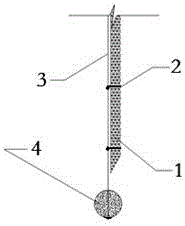
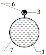
[0033] The concrete pouring structure of large-volume special-shaped stiff columnar yo-column tubes on the ground, the material of the prefabricated concrete yo-yo 4 is the same as that of the rigid column concrete, the diameter of the prefabricated concrete yo-yo 4 is 60mm, and the soft tube 1 is poured through the standard connection. The barge is processed in sections, each joint is in an inverted cone shape, and the length of each section is 2.4m. The diameter of the pouring soft conduit 1 is the same as that of the concrete prefabricated yo-ball 4. The pouring flexible conduit 1 passes through the conduit through the coil ferrule 2 and the steel wire. 3 are connected in series, the arrangement distance of the catheter through the coil hoop 2 is 1.2m, the catheter through the coil hoop 2 includes the through coil 6 and the catheter hoop 7, the through coil 6 is fixedly connected with the catheter hoop 7, and the through coil 6 is fixedly connected The steel wire 3 is fixedl...

Embodiment 2

[0035] The method for concrete pouring using the above-ground large-volume special-shaped rigid column yo-ball type conduit string concrete pouring structure described in Example 1 specifically includes the following steps:

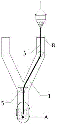
[0036] Step 1: Pre-embed the string pipe 5 on the pouring hole of the stiffening plate at the inflection point of the special-shaped rigid column;

[0037] The second step: with the help of the self-weight of the concrete prefabricated yo-ball 4 , slide the pouring soft conduit along the inner wall of the column and the string tube 5 at the inflection point to the bottom of the special-shaped rigid column through the steel wire 3;

[0038] Step 3: Connect the top connecting port of the pouring flexible conduit 1 with the concrete hopper, and start pouring;

[0039] Step 4: During the pouring process, the flow rate of the concrete in the pipeline is 0.5m / s. According to this flow rate, the pulling delay time of the pouring flexible conduit 1 is controlled ...

Embodiment 3

[0041] The structure and connection relationship of each part of the above-ground large-volume special-shaped rigid column yo-ball type conduit series pipe concrete pouring structure described in this embodiment are the same as those in Embodiment 1, and the different technical parameters are:

[0042] 1, the diameter of concrete prefabricated yo-ball 4 is 70mm;

[0043] 2. The length of each section of pouring soft conduit 1 is 2.7m;

[0044] 3. The layout spacing of the catheter through the coil ferrule 2 is 1.6m;

[0045] 4. The diameter of the coil 6 is 1.18 times the diameter of the steel wire 3;

[0046] 5. The diameter of the conduit collar 7 is 1.1 times the diameter of the pouring flexible conduit 1;

[0047] 6. The specification of the steel wire 3 is 2.5mm;

[0048] 7. The string pipe 5 is 225mm in length;

[0049] 8. The diameter of the large mouth of the string pipe 5 is 2.2 times the diameter of the pouring flexible conduit 1, and the diameter of the small open...


PUM

PropertyMeasurementUnit
diameteraaaaaaaaaa
lengthaaaaaaaaaa

Abstract

The invention relates to the technical field of concrete pouring of the construction industry, in particular to a rolling ball type concrete pouring structure and method for an overground large special-shaped stiff column. According to the method, a flexible pouring guide pipe is connected in series with a steel wire through small steel rings in a full-length mode, through the dead weight of a concrete ball, the flexible pouring guide pipe is released to the bottom of the special-shaped column in a rolling mode along string pipes located on the inner wall and inflection point portions of a column body by means of the steel wire, and then a top connecting opening of the guide pipe is connected with a discharge outlet of a hopper or a pump pipe; and in the pouring process, the burying depth of the discharge outlet of the guide pipe is kept until pouring is completed. According to the structure and method, the guide pipe is adopted for pouring construction, the concrete pouring conveying path is independent and is prevented from being separated due to space blocking of steel bars, steel ribs and the like in the column body, and the blending quality and performance of concrete in the pouring position are guaranteed. Tower crane hopper feeding, or mechanical pumping or other ways can be flexibly selected for column body concrete pouring according to field conditions, so that the efficiency of column body concrete pouring is improved.

Description

technical field [0001] The invention relates to the technical field of concrete pouring in the construction industry, in particular to a concrete pouring structure and method suitable for various types of conventional or special-shaped rigid columns with large steel content and complex internal structures. Background technique [0002] At present, large-scale commercial projects and public facilities are displayed around people's lives like a spring. While pursuing large volumes and large spaces, they are constantly innovating and creating new ones, strengthening the recognition of buildings in terms of structural design and architectural forms, and striving to Competing for the image of the city's central landmark, the resulting rigid structure has become the new favorite of this type of architectural design. In order to improve the load-bearing capacity of such vertical space load-bearing members and control the resulting technical defects of large cross-section and heavy ...

Claims


Application Information

Patent Timeline
Patent Type & Authority Applications(China)
IPC IPC(8): E04G21/02E04C3/34
CPCE04C3/34E04G21/02
Inventor 李洪杰张强白羽赵传莹俞涵
Owner DALIAN BRANCH OF CHINA CONSTR EIGHTH ENG DIV CORP
Why Eureka
Try Eureka