
Object surface deformation feature extraction method based on line scanning three-dimensional point cloud

A technology of object surface and 3D point cloud, applied in image data processing, instrument, character and pattern recognition, etc., can solve problems such as inability to meet measurement requirements

Active Publication Date: 2016-07-27
WUHAN WUDA ZOYON SCI & TECH
View PDF6 Cites 27 Cited by
  • Summary
  • Abstract
  • Description
  • Claims
  • Application Information

AI Technical Summary

Problems solved by technology

This method can be used for fixed site monitoring where objects slowly deform. However, in aspects such as road defect detection, tunnel measurement, track defect detection, online chip weak defect detection, and cultural relic archaeology, etc., it is required to measure in a high-speed dynamic environment, and requires a The measurement can obtain a measurement section in the strict sense, that is, the points on the section are measured at the same attitude and at the same time, such as road rutting detection, the measurement width is at least 2000 mm, and the measurement resolution (points on the same section use intervals) at least reaches mm, the distance measurement accuracy reaches 0.01 mm, and the measurement frequency is above 10KHz, which is equivalent to measuring 200 million points per second. The existing laser three-dimensional radar measurement technology cannot meet the measurement requirements

Method used


Image

  • Object surface deformation feature extraction method based on line scanning three-dimensional point cloud
  • Object surface deformation feature extraction method based on line scanning three-dimensional point cloud
  • Object surface deformation feature extraction method based on line scanning three-dimensional point cloud

Examples


Embodiment 1

[0139] 1) Knowledge base

[0140] The embodiment of the technical solution of the present invention takes asphalt pavement crack recognition as an example to describe a method for extracting features of asphalt pavement cracks based on line scanning three-dimensional point cloud.

[0141] Asphalt pavement crack feature knowledge base information includes: pavement texture model, crack length > 10cm, crack depth > 1mm, crack directionality (horizontal crack, longitudinal crack, crack, block crack), continuity, aggregation, crack on the cross-section In the outline, there is a small area deformation, the crack is located below the pavement surface, the crack depth is greater than the general pavement texture depth, the crack has a certain width, the crack has the area characteristic, and the crack has the damage degree characteristic.

[0142] Among them, the calculation method of the crack area, the category of the crack direction, and the degree of crack damage can be defined ...

Embodiment 2

[0158] 1) Knowledge base


PUM

PropertyMeasurementUnit
Lengthaaaaaaaaaa

Abstract

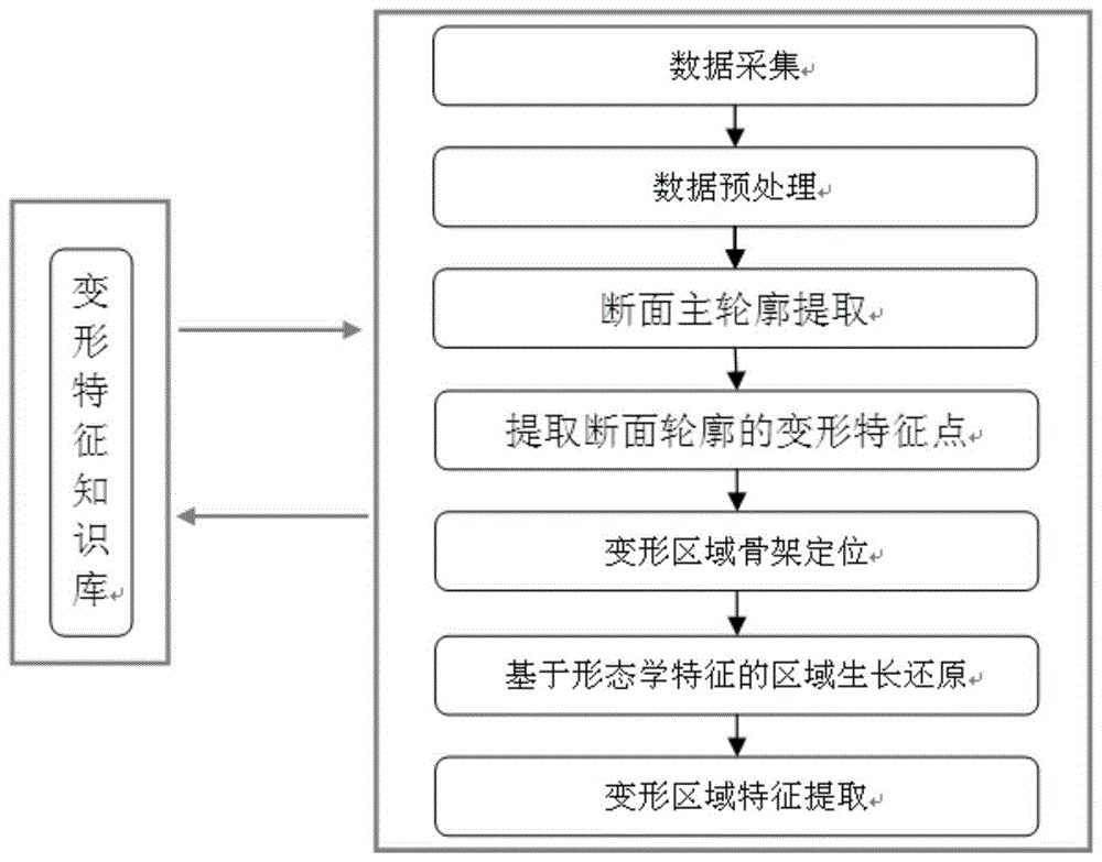
The invention discloses an object surface deformation feature extraction method based on a line scanning three-dimensional point cloud. The method comprises the following steps: data acquisition is performed by use of a three-dimensional measurement sensor based on line structure optical scanning, and three-dimensional point cloud data of the surface of an object is obtained after data preprocessing; influences exerted by abnormal data and textures on a main contour of a section are eliminated, and the main contour of the section of the object is accurately obtained; through combination with a deformation feature database, binary images are obtained by extracting deformation feature points on the basis of the section, and an object form subblock set is obtained by preliminarily positioning a deformation area on the basis of subblock images; then a region of confidence (ROC) is generated by performing morphological operation on the deformation feature points in the subblock set, next, an object is restored by performing area growth by use of a geometric form feature of the ROC, and thus the detection integrity of the deformation area is ensured; and finally, according to a predefined deformation feature, a deformation feature value of the deformation area at the surface of the object is counted, and accordingly, complete attribute information of object deformation is accurately obtained.

Description

technical field [0001] The invention relates to the technical field of surface detection, in particular to the technical field of object deformation feature extraction methods. Background technique [0002] With the advancement of social science and technology, people's requirements for the quality of objects are getting higher and higher, even reaching the state of "nearly perfect". When an object is stressed, it will show mechanical properties such as deformation and failure. It is one of the important contents of material science to make the material serve within the failure limit range, and at the same time have better stability and economy. Due to production defects or wear and tear, various deformations (such as cracks, holes, road rutting, track bending, lining deformation, can deformation, pipe deformation, etc.) may appear on the surface of the object, which will affect the performance of the object and even cause safety accidents. Therefore, timely detection of ob...

Claims


Application Information

Patent Timeline
IPC IPC(8): G06T7/00G06K9/32
CPCG06T7/0002G06T2207/10028G06V10/25G06V20/625
Inventor 李清泉曹民张德津林红陈颖
Owner WUHAN WUDA ZOYON SCI & TECH
Learn More