Small-size ultra wideband power divider

An ultra-broadband, power divider technology, applied in waveguide-type devices, electrical components, connecting devices, etc., can solve the problem of large size of the power divider, and achieve the effects of increasing inter-frequency isolation, reducing cost, and reducing size

Active Publication Date: 2016-07-27
TONGYU COMM INC
View PDF4 Cites 1 Cited by
  • Summary
  • Abstract
  • Description
  • Claims
  • Application Information

AI Technical Summary

Problems solved by technology

[0003] The technical problem to be solved by the present invention is to overcome the problem of large p

Method used


Image

  • Small-size ultra wideband power divider
  • Small-size ultra wideband power divider
  • Small-size ultra wideband power divider

Examples


Example Embodiment

[0018] The following describes the embodiments of the present invention in detail with reference to the drawings.

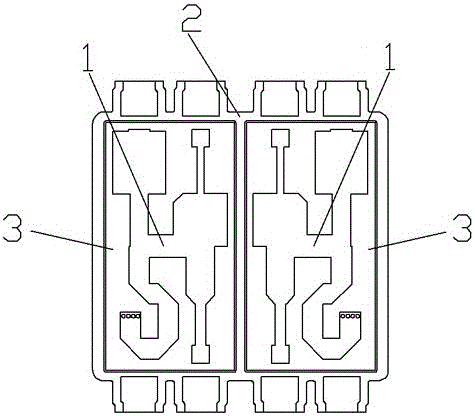
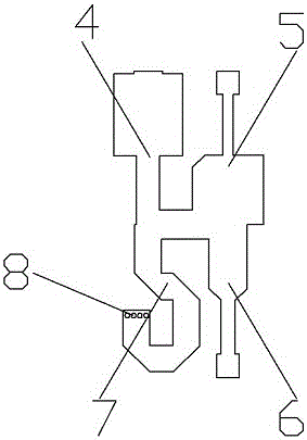
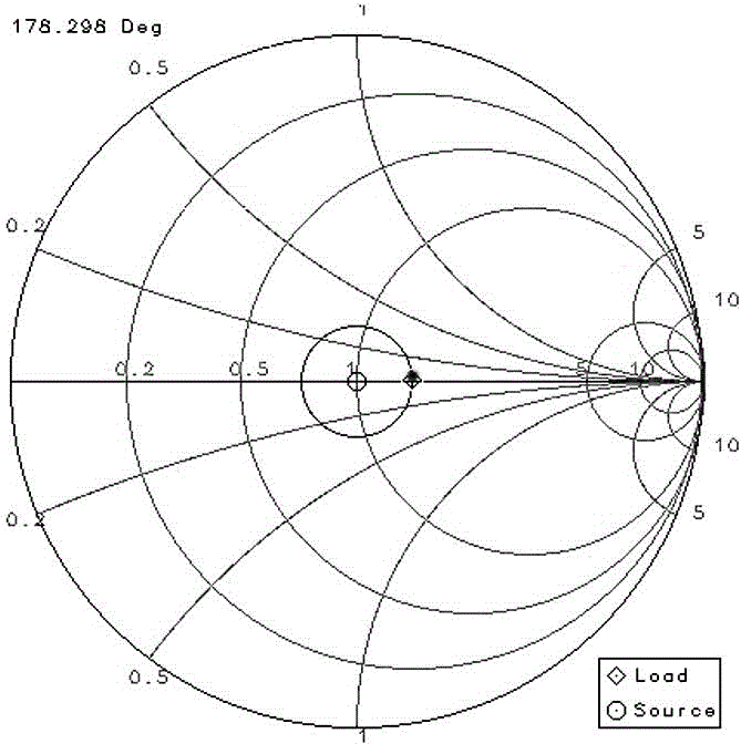
[0019] Such as figure 1 As shown, a small-size ultra-wideband power divider includes a circuit board 3 and a power dividing circuit 1 arranged on the circuit board 3. The circuit board in this embodiment is provided with two identical power dividing circuits. Each power division circuit 1 is like figure 2 As shown, there is an input signal transmission section 4 connected to the input port of the power divider and two output signal transmission sections 5 and 6 connected to the output port. The input signal transmission section and the output signal transmission section are electrically connected through a circuit node. The electrical signal passing through the input signal transmission section 4 is divided into two at this node and distributed to the output signal transmission sections 5 and 6. Such as image 3 In the Smith chart shown, the impedance of the RF cir...


PUM


Abstract

The invention provides a small-size ultra wideband power divider, comprising a circuit board and a power division circuit arranged on the circuit board, wherein the power division circuit is provided with an input signal transmission segment connected to an input port and two output signal transmission segments connected to an output port, the input signal transmission segment and the output signal transmission segments are electrically connected by a circuit node, signal transmission path lengths of the input signal transmission segment and the output signal transmission segments are 1/6 lambda to 1/9 lambda, and a circuit matching segment used for matching line impedance and having a signal transmission path length of1/3 lambda to 1/6 lambda is further connected at the circuit node of the input signal transmission segment and the output signal transmission segments. The size of the power divider is reduced, so the power divider can be applied to more environments. The problems of line capacitance and inductance effects and impedance mismatch resulting from a shortened signal transmission branch length are overcome, and the performance of the power divider is guaranteed.

Description

technical field [0001] The invention relates to a power splitter for an antenna, in particular to a small-sized ultra-wideband power splitter. Background technique [0002] The full name of the power divider is the power divider. It is a device that divides the energy of one input signal into two or more outputs with equal or unequal energy. It is the basic element in the antenna array feed network. With the development of technology, people have higher and higher requirements for the miniaturization of devices, and the miniaturization and broadband of power splitters have always been the research direction in the industry. Impedance matching is a common working state in radio technology, which reflects the power transfer relationship between the input circuit and the output circuit. Maximum power transfer is achieved when circuits are impedance matched. On the contrary, when the impedance of the circuit is mismatched, not only the maximum power transmission cannot be obta...

Claims


Application Information

Patent Timeline
IPC IPC(8): H01P5/16
CPCH01P5/16
Inventor 苏国成岳彩龙石磊曹林利许跃权韩波刘木林
Owner TONGYU COMM INC
Why Eureka
Try Eureka