A microgrid auxiliary master-slave control method based on improved droop control

A control method and micro-grid technology, applied in the direction of power network operating system integration, electrical components, circuit devices, etc., can solve the problems of the inverter being unable to achieve output power, poor power control regulation, and power distribution limitations, etc. Effects of enhanced stability, improved voltage drop, improved steady state performance

Active Publication Date: 2018-09-28
SHANGHAI UNIVERSITY OF ELECTRIC POWER
View PDF3 Cites 2 Cited by
  • Summary
  • Abstract
  • Description
  • Claims
  • Application Information

AI Technical Summary

Problems solved by technology

[0004] Droop control (droop) technology draws on the idea of ​​parallel control of synchronous generators, which can realize the peer-to-peer parallel connection of multiple inverters, and can automatically distribute the active and reactive power of DG, but the classic droop control has limitations for power distribution.
Due to the uncertainty of the line impedance of the microgrid and the output impedance of the inverter, the inverter cannot achieve output power coupling, and the droop characteristics need to be different according to the inductive, resistive, and capacitive properties of the line. In addition, as a droop control The power control loop of the outer loop structure of the system also plays an important role in the stable control of the system frequency, etc., but the power control is essentially a differential regulation, and a large load change in the island will cause a deviation of the frequency, etc., and it is necessary to ensure the droop characteristics and regulation rapidity

Method used


Image

  • A microgrid auxiliary master-slave control method based on improved droop control
  • A microgrid auxiliary master-slave control method based on improved droop control
  • A microgrid auxiliary master-slave control method based on improved droop control

Examples


Embodiment

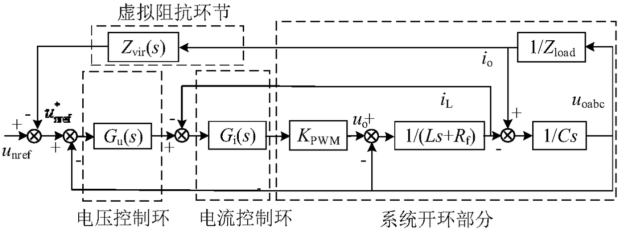
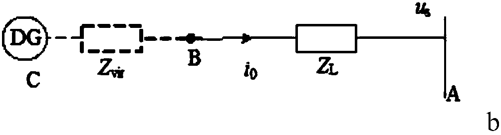
[0049] The new type of droop control adopted in the present invention: firstly, on the basis of the control principle of the ring inverter voltage loop current loop, power decoupling is effectively realized by adding a dynamic damping impedance link to serve the power control loop; secondly, the power control link is improved Mainly by combining the frequency difference f-fn with the voltage difference U-U 0 As a feedback signal, in addition to adding a PI control link to the feedback line, the droop coefficient of the feedback line needs to be corrected to form a new type of droop control method. In addition, since there is no integral term in the reactive power expression, In the steady state, the voltage has a static difference and the robustness is poor, so it is necessary to add an integral link to the reactive power control circuit.

[0050]The above method is called new droop control, and it is applied to the master-slave control microgrid system as an auxiliary unit. ...


PUM


Abstract

The invention relates to an improved droop control based microgrid auxiliary master-slave control method. The method is used for maintaining stability of the voltage and power of the microgrid. The microgrid comprises multiple DGs connected with alternating current buses respectively; each DG comprises a master-control DG, an auxiliary DG and a slave-control DG; the master-control DG and the slave-control DG are used as a master-control unit and a slave-control unit in the master-slave control method respectively; the inverter in the auxiliary DG adopts voltage and current dual-loop control; a load current io is multiplied by a dynamic virtual impedance Zvir, and the obtained product is used as an instruction voltage to be added in a feedback signal to a voltage loop, so that the output impedance of the inverter is sensitive. Compared with the prior art, the inverter of the auxiliary DG adopts the dynamic virtual impedance, so that matching between the output impedance of the inverter and the circuit impedance can be ensured, voltage drop can be effectively relieved, and the power quality is ensured; and in addition, the improved droop control is adopted, and an integral link is introduced in the reactive power control link, so that steady state voltage without static errors is realized, and the steady state performance of the system is improved.

Description

technical field [0001] The invention relates to a coordinated control method for a microgrid, in particular to an auxiliary master-slave control method for a microgrid based on improved droop control. Background technique [0002] With the rapid development of the national economy, energy and environmental issues have become increasingly prominent, and micro-grid technology based on renewable energy has emerged as the times require. The concept of micro-grid is helpful to improve the utilization and flexibility of distributed generation (DG). How to control the coordinated control of multiple distributed power sources in the microgrid and smoothly switch between grid-connected / islanded modes is an urgent problem to be solved. [0003] Microgrid control modes are mainly divided into peer-to-peer control, hierarchical control, and master-slave control. The peer-to-peer control strategy considers that the status of the internal power sources of the microgrid is equal, and "plu...

Claims


Application Information

Patent Timeline
Patent Type & Authority Patents(China)
IPC IPC(8): H02J3/14H02J3/38
CPCH02J3/14H02J3/38H02J3/388Y02B70/3225Y02P80/14Y04S20/222
Inventor 程启明褚思远杨小龙张强黄山张海清
Owner SHANGHAI UNIVERSITY OF ELECTRIC POWER
Why Eureka
Try Eureka