Electric vehicle wheel hub system and driving, braking and electric energy compensation method for the same
An electric wheel hub, electric vehicle technology, applied in electric vehicles, motors, electromechanical devices, etc.
- Summary
- Abstract
- Description
- Claims
- Application Information
AI Technical Summary
Problems solved by technology
Method used
Image

Examples
Embodiment 1
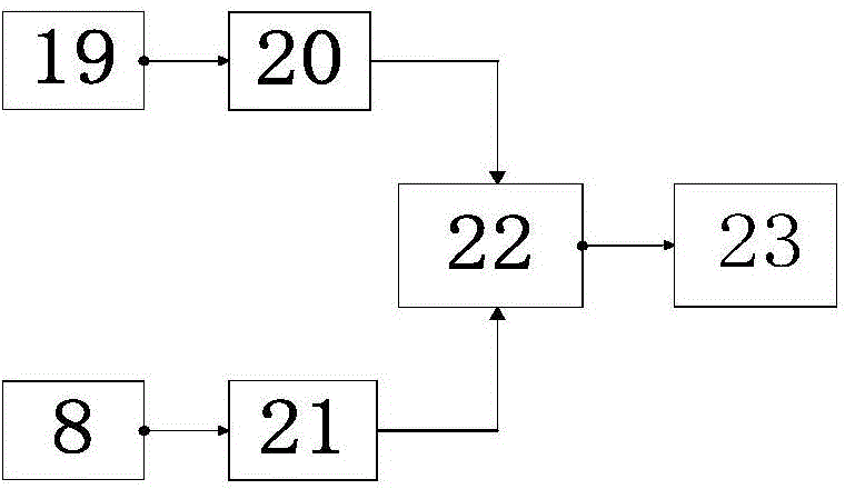
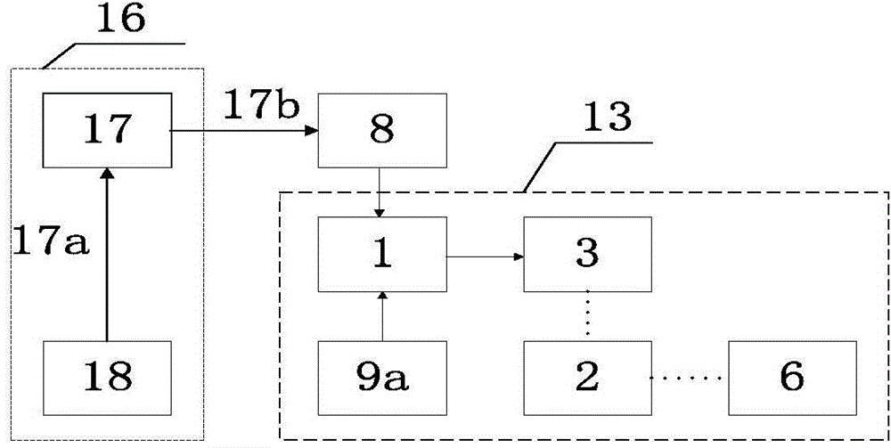
[0101] A wheel hub system of a power-assisted electric tricycle, including an electric hub device 13, a battery pack 8 and a range-extending system 16; the electric hub device is arranged on the front wheel, and its supporting frame 4 and mechanical partial schematic structure are as follows: Figure 10a As shown; the battery pack 8 selects a nominal 48V20Ah lead-acid gel battery and is installed on the lower part of the frame; the range-extending system uses a methanol generator system as an electric energy supplement device 18, and the generator system consists of a methanol fuel tank, a methanol internal combustion engine, and a generator It is combined with a rectifying device; the logic charging device 17 of the range-extending system is mainly composed of functional modules such as a battery pack real-time voltage monitoring module, a constant voltage limited current charging module and a working logic control module, and its input terminal 17a is electrically connected to...
Embodiment 2
[0110] The power supply device of the range-extending system in Example 1 is changed from a methanol generator system to an aluminum-air primary battery; the power modulator 1 is implemented using pulse digital technology, and the core module includes a conventional CPU and a drive module with a design power of 1500W. working logic like Figure 5b As shown, the pulse conversion conditioning circuit is mainly to complete the conversion of the pulse signal into a ladder wave signal, the pulse signal generator mainly generates the required pulse signal, and secondly outputs the peak pulse through the differential circuit, and then passes through the limiting circuit to convert the negative of the peak pulse The half-cycle is filtered out, and the positive half-axis peak pulse is left. The integral circuit composed of an integrated operational amplifier is used for integral accumulation, and a voltage comparator and a control circuit are added to form a complete ladder pulse signal...
Embodiment 3
[0114] Using T on the basis of Example 2 2 Time-domain electrification adds an electromagnetic force braking function to the electric hub device.
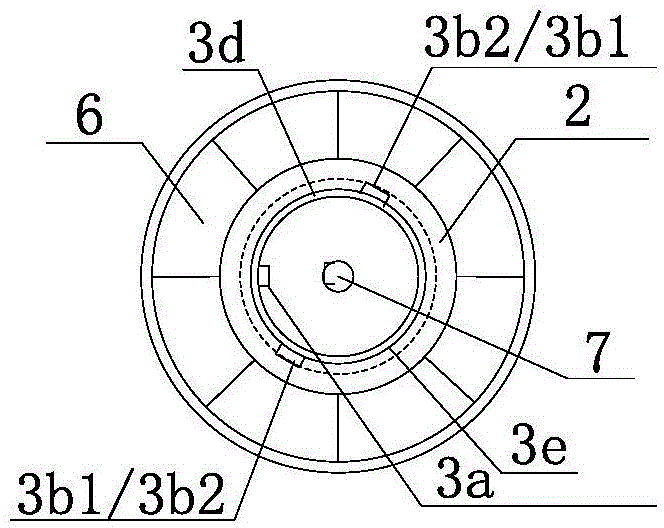
[0115] The power supply modulator correspondingly adds a braking signal input terminal 1e to electrically connect the electromagnetic braking device 9b, such as Figure 5c As shown, the electromagnetic braking device is a ten-stage rheostat; when the manual control electromagnetic braking device sends a braking signal, the power modulator cuts off T 1 corresponding to the timing current, start T 2 Time-domain energization, the brake energization time domain is set when the sensing unit 3c senses the rotor unit 3b around the shaft to 5 degrees to The time period for the 0 position.
[0116] The brake current output by the power modulator corresponds to the ten-level resistance of the electromagnetic braking device 9b, which is set to ten-level intensity. The set output current intensity is: the first level is 5A, the last leve...
PUM
 Abstract
Description
Claims
Application Information
 - R&D
- Intellectual Property
- Life Sciences
- Materials
- Tech Scout
- Unparalleled Data Quality
- Higher Quality Content
- 60% Fewer Hallucinations
Browse by: Latest US Patents, China's latest patents, Technical Efficacy Thesaurus, Application Domain, Technology Topic, Popular Technical Reports.
© 2025 PatSnap. All rights reserved.Legal|Privacy policy|Modern Slavery Act Transparency Statement|Sitemap|About US| Contact US: help@patsnap.com