Direct air-intake sludge drying apparatus and method thereof

A sludge drying and air intake technology, which is applied in the direction of temperature control sludge treatment, dewatering/drying/concentrating sludge treatment, etc. Effect

Pending Publication Date: 2016-08-03
广州正晟科技有限公司
View PDF8 Cites 2 Cited by
  • Summary
  • Abstract
  • Description
  • Claims
  • Application Information

AI Technical Summary

Problems solved by technology

[0006] The present invention proposes a direct air-intake sludge drying device in a single form, wherein the sludge is continuously sheared, crushed and turned by the turning device arranged in the first drying chamber, and the first drying chamber The outlet pipe array on at least one inner wall blows drying gas to the sludge in the first drying chamber 6a, so that the sludge is in frequent contact with the drying gas, thereby solving the problem of uneven internal and external dryness during the sludge drying process question

Method used


Image

  • Direct air-intake sludge drying apparatus and method thereof
  • Direct air-intake sludge drying apparatus and method thereof
  • Direct air-intake sludge drying apparatus and method thereof

Examples


Embodiment Construction

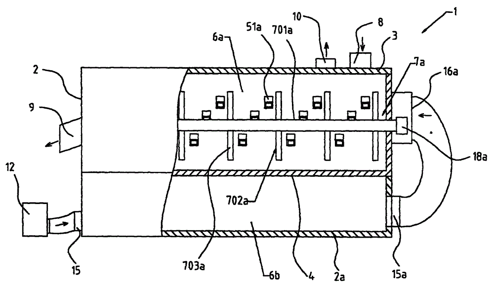
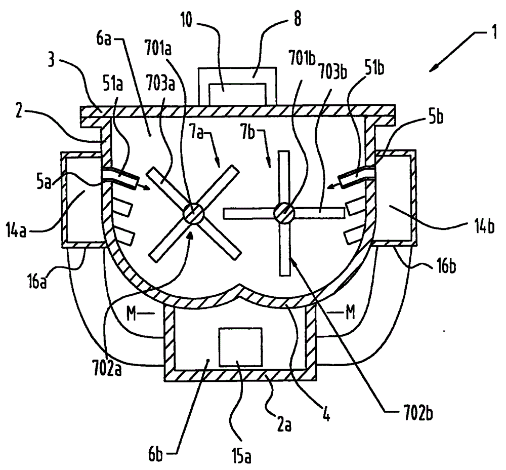
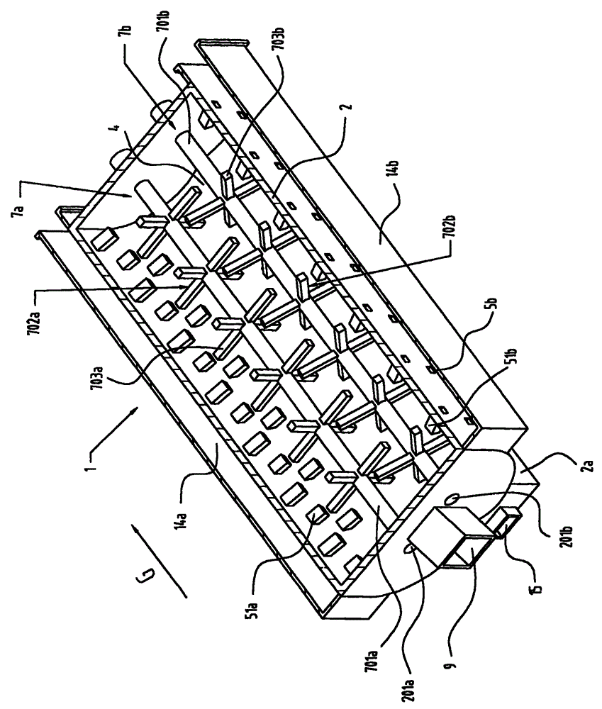
[0040] figure 1 A preferred embodiment of the direct-inlet type sludge drying device of the present invention is shown, and figure 2 Yes figure 1 A cross-sectional view of the sludge drying device in , which schematically shows a single-body sludge drying device. The direct-inlet type sludge drying device 1 includes a casing, wherein the casing includes an upper casing 2 , a lower casing 2 a and an upper cover (or cover) 3 . The bottom of the upper casing 2 serves as a partition wall 4 that divides the inner space of the casing into the first drying chamber 6a and the second drying chamber 6b. The upper casing 2 and the upper cover 3 constitute the first drying chamber 6a, and the bottom of the lower casing 2a and the upper casing 2, that is, the partition wall, constitutes the second drying chamber 6b. As shown in the figure, although the first drying chamber 6a and the second drying chamber 6b are arranged one above the other, other arrangements are also possible. Howev...


PUM


Abstract

The invention provides a direct air-intake sludge drying apparatus. The direct air-intake sludge drying apparatus comprises a casing, wherein, a dividing wall is arranged in the casing, so that the space in the casing is divided into a first drying chamber and a second drying chamber. A feed inlet and an air outlet are arranged on the upper part of the first drying chamber, and a discharge hatch is arranged on the circumferential wall of the first drying chamber. An air inlet and the air outlet are arranged on the circumferential wall or the bottom of the second drying chamber. A sludge stirring apparatus is arranged in the first drying chamber, wherein, the sludge stirring apparatus comprises a rotation shaft and a stirring component fixed on the rotation shaft. A distribution chamber is arranged at the outboard of a side wall of the first drying chamber, the air inlet and the side wall adjacent to the first drying chamber have the through holes, and the side wall of the first drying chamber drying chamber has the through hole. The through hole on the side wall of the first drying chamber is communicated with the side wall of the distribution chamber, and is communicated with the air outlet of the second drying chamber and the air inlet of the distribution chamber. The invention also provides a direct air-intake sludge drying method by using the direct air-intake sludge drying apparatus.

Description

technical field [0001] The present invention relates to the field of sludge drying, and generally relates to a direct air-inlet sludge drying device, in particular to a direct air-inlet sludge drying device in the form of a single unit and the use of such sludge A drying device for sludge drying. Background technique [0002] Effective treatment of sludge is very important in the sewage treatment process. Usually, sewage treatment plants use concentration and dehydration methods to reduce the water content of sludge from more than 90% to about 60-80%, and then landfill, solidify or dry it. Landfill is easy to ferment sludge and cause secondary pollution to the environment. However, the existing solidification or drying equipment consumes a large amount of waste in the process of sludge treatment due to its strong viscosity, easy caking, and difficult to break. Energy, therefore, is difficult to reduce costs and improve efficiency, and cannot meet the needs of treating a la...

Claims


Application Information

Patent Timeline
Patent Type & Authority Applications(China)
IPC IPC(8): C02F11/12C02F11/18
Inventor 谭玮
Owner 广州正晟科技有限公司
Why Eureka
Try Eureka