Optical fiber processing technology

A processing technology and optical fiber technology, applied in the direction of manufacturing tools, glass fiber drawing devices, glass manufacturing equipment, etc., can solve the problems of high production environment temperature, waste of heat energy, inconsistent wire diameter, etc., to improve energy utilization rate and improve the processing environment , Guarantee the effect of drawing quality

Active Publication Date: 2018-05-11
HANGZHOU FUTONG COMM TECH CO LTD
View PDF4 Cites 2 Cited by
  • Summary
  • Abstract
  • Description
  • Claims
  • Application Information

AI Technical Summary

Problems solved by technology

Existing optical fiber drawing furnaces mainly include graphite resistance furnaces, graphite induction furnaces, etc. During the drawing process, temperature is the key control parameter. During the heating process, if the preform is heated unevenly, the viscosity of each part of the preform will be different. That is, the viscous state of the glass body is different during the wire drawing forming process. At the same drawing speed, the part that absorbs more heat has a fast temperature rise, low viscosity, and is prone to accumulation; while the part that absorbs less heat and has a slow temperature rise will be insufficiently formed. , which leads to poor ellipticity of the formed wire on the same section, and serious inconsistency of wire diameter within a certain length range
[0003] The existing optical fiber drawing furnace is fixed, it is difficult to ensure the coaxiality of the glass rod and the furnace, and there will still be uneven heating of the preform along the circumferential direction, which brings great difficulty to the drawing process; and because the prefabricated The material properties of rods and auxiliary rods. When the optical fiber drawing furnace is working, the light of the heating element will pass through the preform and auxiliary rods. This not only wastes heat energy, but also leads to a higher temperature in the production environment, which is relatively harsh.

Method used


Image

  • Optical fiber processing technology
  • Optical fiber processing technology
  • Optical fiber processing technology

Examples


Embodiment Construction

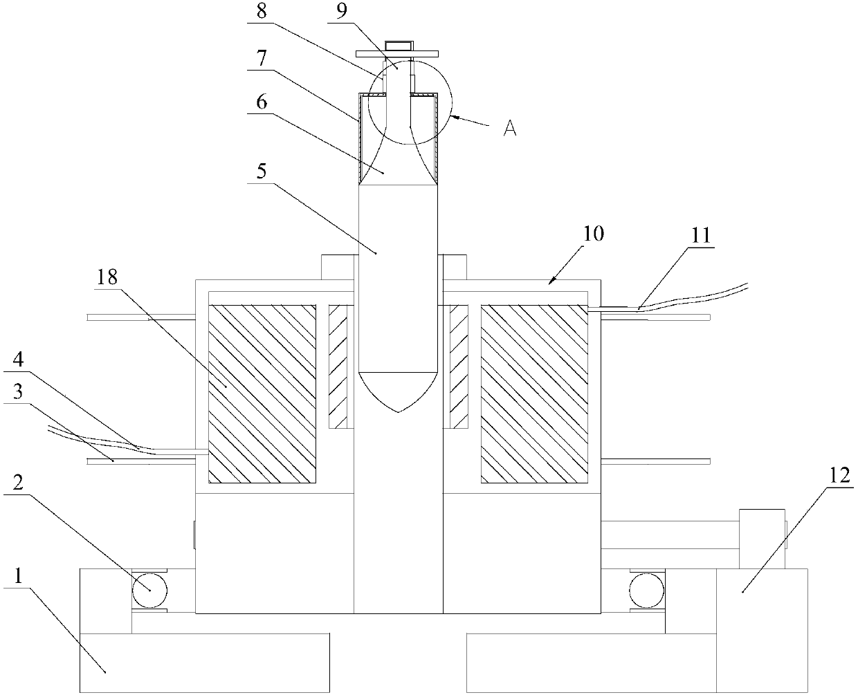
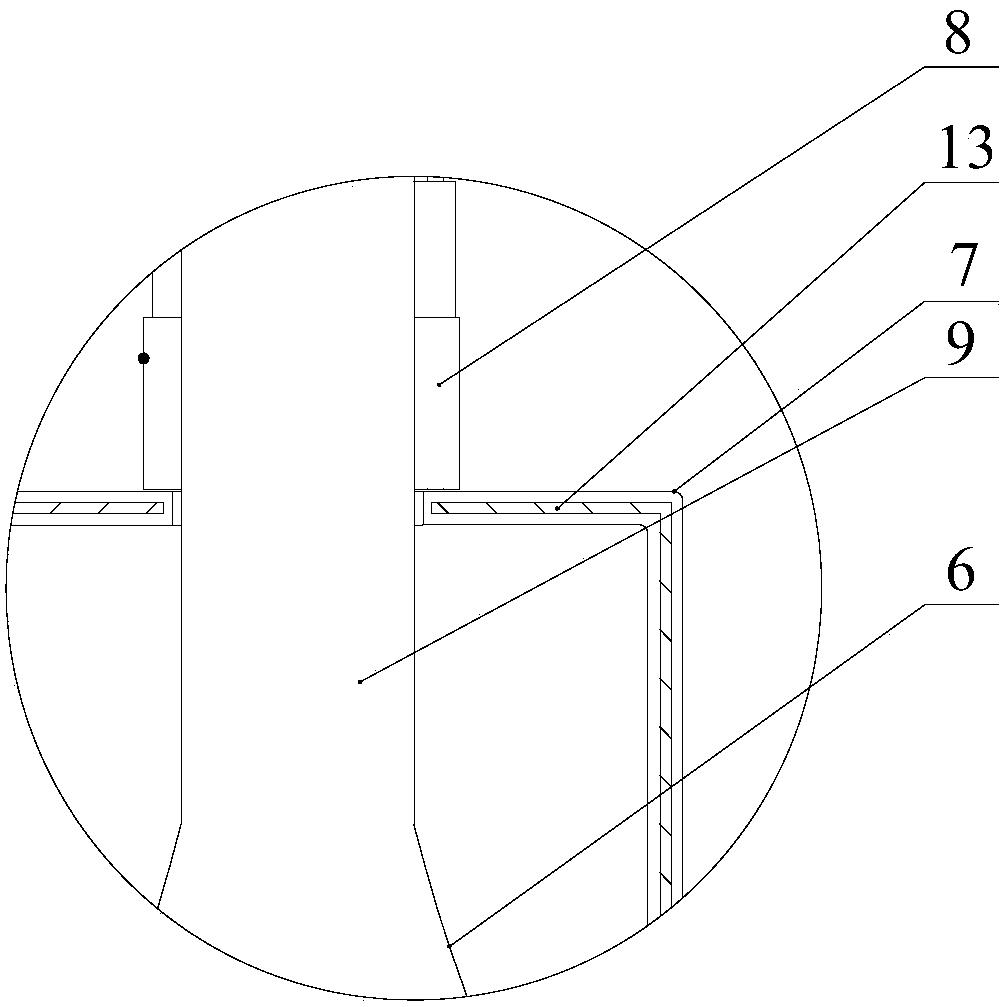
[0037] Below in conjunction with each accompanying drawing, the present invention is described in detail.

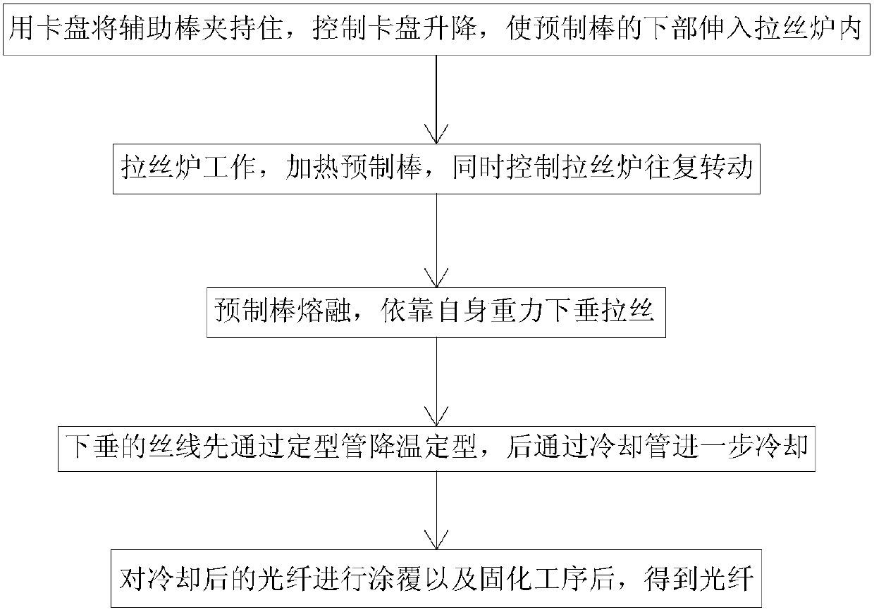
[0038] Such as figure 1 As shown, the present embodiment discloses a processing technology of an optical fiber, comprising the following steps:

[0039] 1) Clamp the auxiliary rod with the chuck, control the lifting of the chuck, so that the lower part of the preform rod extends into the drawing furnace;

[0040] 2) The wire drawing furnace is working, heating the preform, and at the same time controlling the reciprocating rotation of the wire drawing furnace;

[0041] 3) The preform is melted and drawn down by its own gravity;

[0042] 4) The drooping silk thread is first cooled and shaped by the shaping tube, and then further cooled by the cooling tube;

[0043] 5) After the cooled optical fiber is coated and solidified, an optical fiber is obtained.

[0044] By controlling the reciprocating rotation of the drawing furnace, this processing technology can ensure tha...


PUM


Abstract

The invention discloses an optical fiber processing process. The optical fiber processing process comprises the following steps: 1) clamping an auxiliary rod by a chuck and controlling the chuck to be lifted up and down for enabling the lower part of a prefabricated rod to extend into a fiber drawing furnace; 2) starting the fiber drawing furnace, heating the prefabricated rod, and controlling the fiber drawing furnace to rotate in a reciprocating manner; 3) melting the prefabricated rod and drooping a drawn fiber by self gravity; 4) shaping the drooped fiber by cooling through a shaping pipe, and further cooling the fiber through a cooling pipe; and 5) coating and solidifying the cooled optical fiber to obtain an optical fiber. According to the processing process, the fiber drawing furnace is controlled to rotate in the reciprocating manner, so that the prefabricated rod can be guaranteed to be heated uniformly in a circumferential direction and the fiber drawing quality is ensured.

Description

technical field [0001] The invention relates to the field of optical fibers, in particular to a processing technology for optical fibers. Background technique [0002] Optical fiber processing includes drawing process, shaping cooling process, coating process and curing process. Existing optical fiber drawing furnaces mainly include graphite resistance furnaces, graphite induction furnaces, etc. During the drawing process, temperature is the key control parameter. During the heating process, if the preform is heated unevenly, the viscosity of each part of the preform will be different. That is, the viscous state of the glass body is different during the wire drawing forming process. At the same drawing speed, the part that absorbs more heat has a fast temperature rise, low viscosity, and is prone to accumulation; while the part that absorbs less heat and has a slow temperature rise will be insufficiently formed. , which leads to poor ellipticity of the formed wire on the sa...

Claims


Application Information

Patent Timeline
Patent Type & Authority Patents(China)
IPC IPC(8): C03B37/029
CPCC03B37/0253C03B37/029C03B2205/74
Inventor 王醒东韩肖明
Owner HANGZHOU FUTONG COMM TECH CO LTD
Why Eureka
Try Eureka