Water permeable ground system and paving method

A ground system and water-permeable technology, applied to pavement details, roads, gutters/curbs, etc., can solve problems such as water-permeable ground failure, and achieve low maintenance costs and long service life

Inactive Publication Date: 2016-08-03
RENCHSAND ECO ENVIRONMENT PROTECTION SCI & TECH CO LTD
View PDF5 Cites 4 Cited by
  • Summary
  • Abstract
  • Description
  • Claims
  • Application Information

AI Technical Summary

Problems solved by technology

[0004] The purpose of the present invention is to provide a permeable floor system and pavement method to solve the technical problem in the prior art that the permeable floor seriously fails after being used for a period of time

Method used


Image

  • Water permeable ground system and paving method
  • Water permeable ground system and paving method
  • Water permeable ground system and paving method

Examples


Embodiment 1

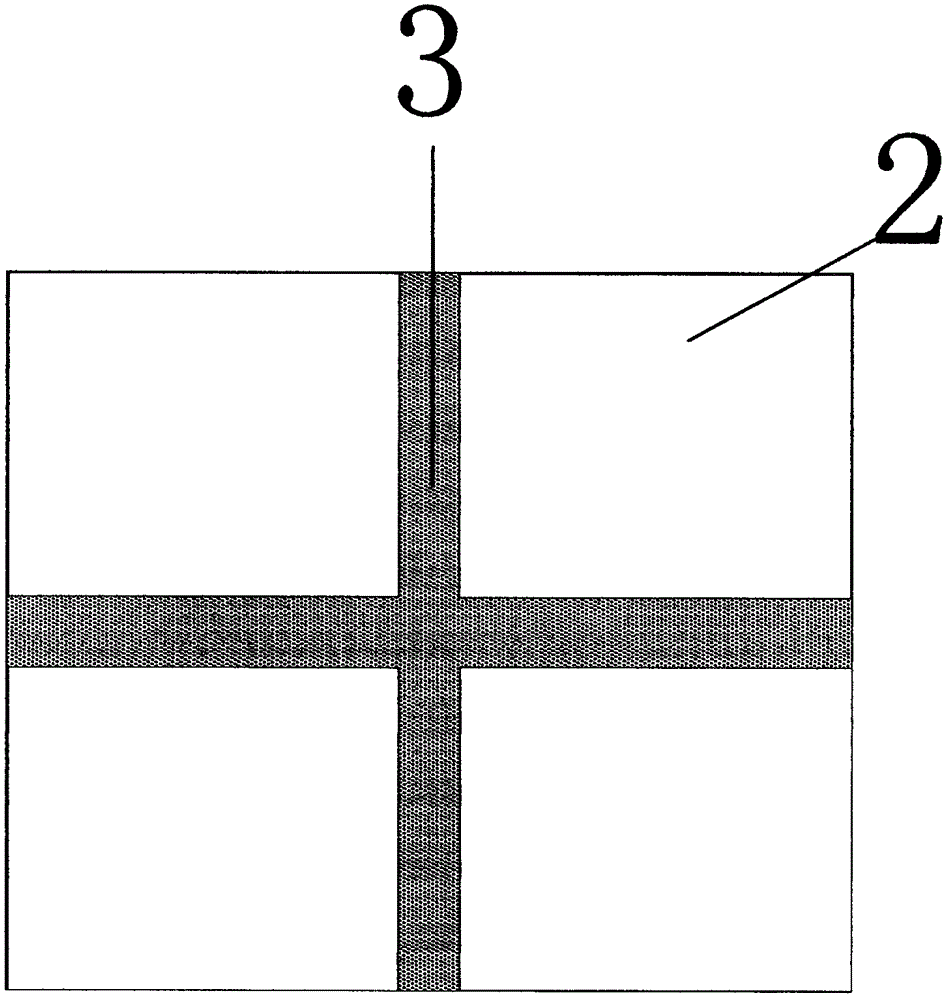
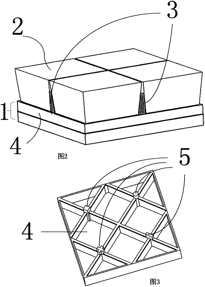
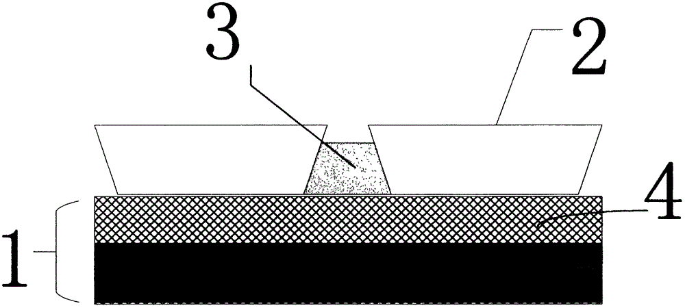
[0046] figure 1 It is a top view of a permeable ground system provided by an embodiment of the present invention. like figure 1 and figure 2 As shown, the permeable surface layer of a permeable floor system provided in this embodiment includes a plurality of permeable bricks 2 and a plurality of permeable strips 3;

[0047] like image 3 As shown, the upper part of the fixed grid 4 has an upwardly protruding fixed post 5 . The shape of the fixed column 5 can be a cylinder, a square column, a strip, a cross, etc., and is not limited to its specific shape.

[0048] Understandably, image 3 For the 4 grid cells in , the shape of the fixed column is different from each other to illustrate that the fixed column can have different shapes. In most cases, the fixed column shapes of each grid cell in the same fixed grid are the same.

[0049] like Figure 11 , as shown in 12, 13, and 14, corresponding to each fixing column 5, an upwardly recessed fixing groove 6 is provided at t...

Embodiment 2

[0060] like Figure 5 As shown, this embodiment is similar to Embodiment 1, the difference is that the cross-sectional shape of the permeable strip 3 is an inverted T shape, and the edge of the permeable brick 2 is also changed accordingly to match the shape of the permeable strip, forming a structure with a narrow top and a wide bottom, which is convenient for water permeability Bar 3 is firmly clamped in the gap.

[0061] In this embodiment, the outer edge of the bottom surface of the permeable brick 2 (the surface in contact with the permeable base 1 ) is hollowed out to form a concave structure with a rectangular cross section, so that the cross section of the permeable brick 2 is T-shaped. Correspondingly, a slot with an inverted T-shaped cross section is formed between two adjacent permeable bricks 2, and the cross-sectional shape of the permeable strip 3 matches the inverted T-shaped slot, so that the permeable strip It can be tightly buckled in the card slot.

[0062...

Embodiment 3

[0064] See Image 6 , this embodiment is similar to Embodiment 1, the difference is that the cross-sectional shape of the permeable strip 3 is rectangular, and the edge of the permeable brick 2 is also changed accordingly to match the shape of the permeable strip, forming a structure with a narrow top and a wide bottom, which is convenient for the permeable strip 3 to be firmly locked set in the gap.

[0065] In this embodiment, the depth of the shallow groove formed on the surface of the permeable strip 3 is the height of the permeable brick 2 minus the height of the concave structure formed at the outer edge of the bottom surface of the permeable brick 2 .

[0066] It can be understood that when two permeable strips 3 intersect, they can be tailored to match the specific environment on site, or a specific intersection shape can be customized as a whole.


PUM


Abstract

The invention provides a water permeable ground system which comprises a water permeable base layer. A fixing grid is buried in the water permeable base layer. A water permeable face layer is arranged on the water permeable base layer and comprises water permeable bricks and water permeable strips. Fixing columns are arranged at the upper portion of the fixing grid and are higher than the upper surface of the water permeable base layer. The water permeable bricks are clamped on the fixing columns. Gaps are formed between the adjacent water permeable bricks. The side walls of the adjacent water permeable bricks and the gaps between the adjacent water permeable bricks form a clamping structure jointly. The water permeable strips are made of a micropore water permeable elastic material and clamped in the gaps. By the adoption of the water permeable ground system, water seeps downwards through the water permeable bricks and the water permeable strips at the same time, the water permeable strips can be conveniently replaced after being aged or blocked, and therefore the service life of the whole water permeable ground system is prolonged. The invention further provides a paving method for the water permeable ground. Due to the fact that the fixing grid is additionally arranged in the water permeable base layer, a leveling layer is not needed, the water permeable bricks are unified in height and equal in interval, and the construction speed is high.

Description

technical field [0001] The invention relates to the technical field of road paving, in particular to a permeable ground system and a paving method. Background technique [0002] With the development of urban construction, the area of ​​non-permeable floor decoration is increasing, the environment is seriously affected, and the urban heat island effect, flood disasters, groundwater depletion and other phenomena are becoming more and more serious. Therefore, it is imminent to increase the urban permeable ground, and products such as permeable ceramic bricks, permeable concrete bricks, and sand-based permeable bricks have emerged as the times require. [0003] However, due to the serious pollution of the urban environment at present, with a lot of dust and other particles, the newly laid various permeable bricks have a relatively ideal water permeability effect. After a period of time, debris, dust and other particles can easily pollute the permeable holes. After cleaning, the...

Claims


Application Information

Patent Timeline
Patent Type & Authority Applications(China)
IPC IPC(8): E01C11/22
CPCE01C11/225
Inventor 胡俊峰
Owner RENCHSAND ECO ENVIRONMENT PROTECTION SCI & TECH CO LTD
Why Eureka
Try Eureka