Noncontact steering angle sensor

A non-contact technology for angle sensors, applied in the field of sensors, can solve problems such as complex calculation formulas, complex installation and calibration, etc., and achieve the effects of reducing complexity, improving anti-interference ability, and small radial size

Active Publication Date: 2016-08-03
QINGDAO SUNSONG GAOKE AUTOMOTIVE ELECTRONICS CO LTD
View PDF7 Cites 5 Cited by
  • Summary
  • Abstract
  • Description
  • Claims
  • Application Information

AI Technical Summary

Problems solved by technology

[0006] The present invention proposes a new non-contact sensor for the complicated calculation formula of the existing angle sensor angle position, the complexity of installation and calibration, etc.

Method used


Image

  • Noncontact steering angle sensor
  • Noncontact steering angle sensor
  • Noncontact steering angle sensor

Examples


specific Embodiment approach

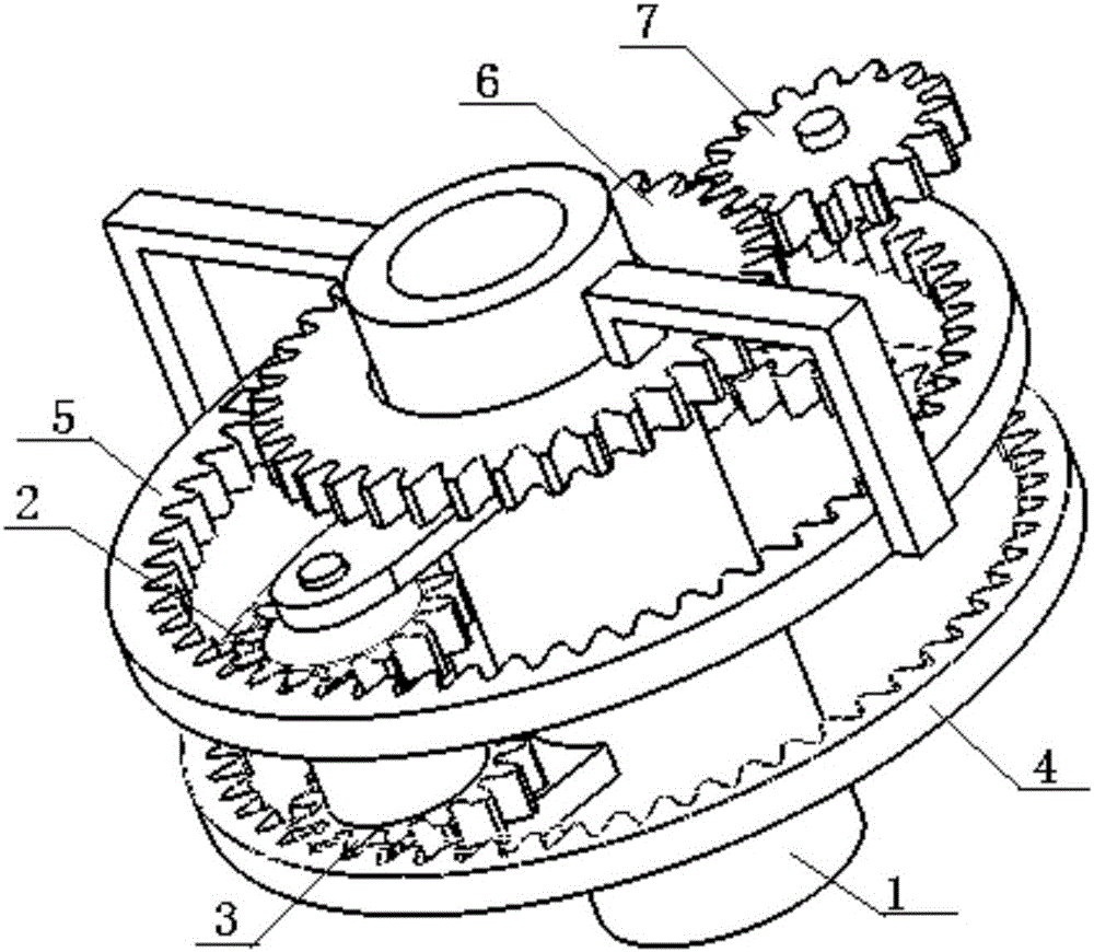
[0029] Such as Figures 1 to 6 As shown, the non-contact angle sensor includes a non-magnetic material housing, and the components installed in the housing include: (1) a sun gear shaft 1 of a non-magnetic material, which is connected to the steering shaft, and at least one set of non-magnetic material is installed on it. The planetary gear set, the planetary gear set is an integral structure, which includes the first planetary gear 3 and the second planetary gear 2; (2) the fixed inner ring gear 4 of non-magnetic material, which is coaxial with the sun gear shaft 1, and is fixed on the casing or It has an integral structure with the shell; (3) the transmission wheel set of non-magnetic material, the transmission wheel set is an integral structure, which is installed coaxially with the sun gear shaft 1, including the transmission inner gear ring 5 and the transmission gear 6; (4) the measurement component, It includes a measuring gear 7 of non-magnetic material, a magnet 8 and...

Embodiment 2

[0032] The structure of embodiment two is basically the same as that of embodiment one, the difference is:

[0033] The sum of the teeth of the fixed internal gear ring and the second planetary gear is equal to the sum of the teeth of the transmission internal gear ring and the first planetary gear. The coaxiality of the two planetary gears and the two inner gear rings is ensured, and at the same time, the radial size of the inner gear rings is reduced to reduce the volume of the sensor.

Embodiment 3

[0035] The structure of embodiment three is basically the same as that of embodiment one, the difference is:

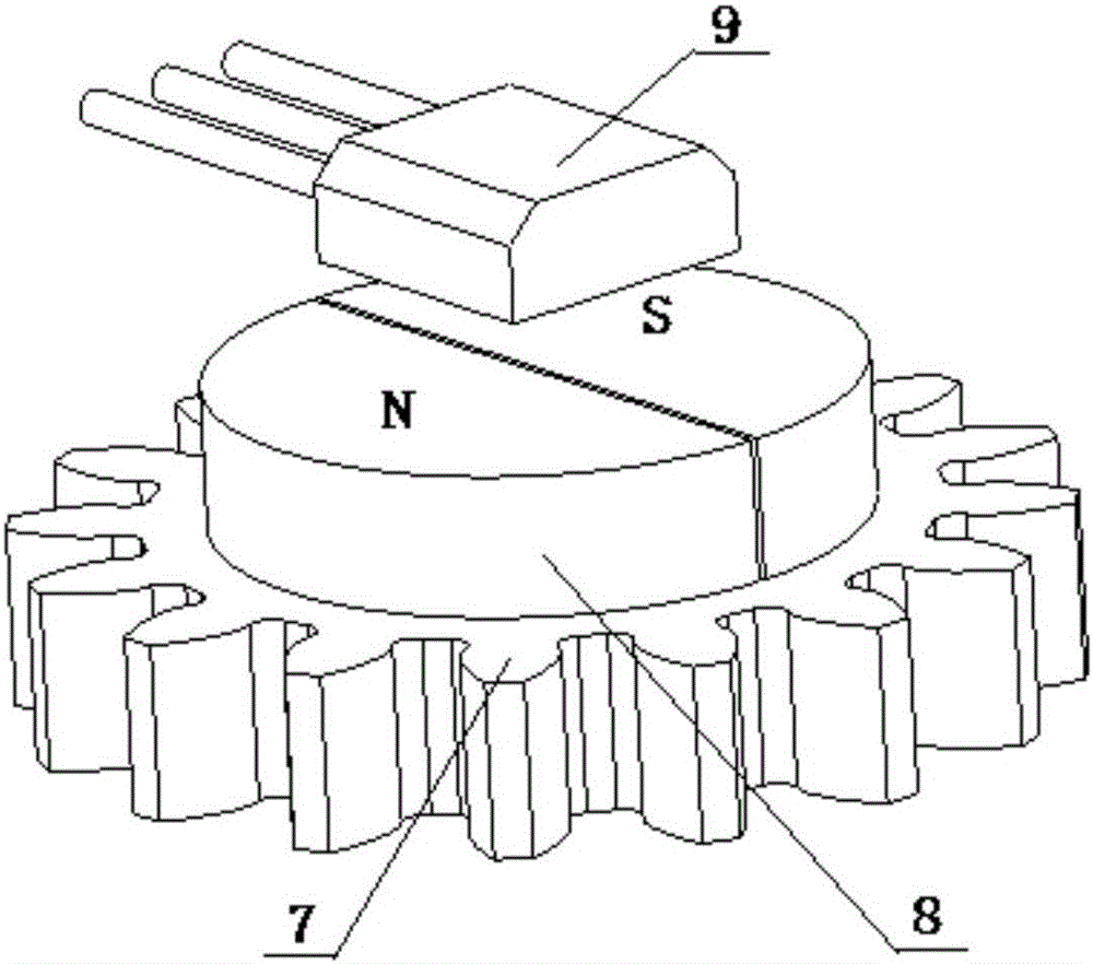
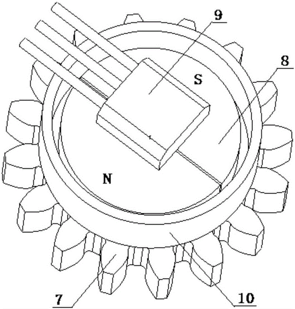
[0036] At least one magnet 8 is installed on the axial surface of the measuring gear 7, and at least one magnetic induction element 9 is installed above the magnet 8, and the magnetic induction element 9 is fixed in the housing of the sensor, leaving a certain gap between the magnet 8 and the magnetic induction element 9.

[0037] The magnetic force line passing through the magnetic induction element 9 starts from the N-level of the magnet 8, passes through the gap between the N-level of the magnet 8 and the magnetic induction element 9, passes through the magnetic induction element 9, and passes through the gap between the magnetic induction element 9 and the S-level of the magnet 8 The gap reaches the S level of the magnet 8, and finally the S level of the magnet 8 reaches the N level of the magnet 8 through the gap between the S level and the N level of the magnet 8...


PUM


Abstract

The invention provides a noncontact steering angle sensor comprising a shell, and a sun wheel shaft, a fixed internal tooth ring, a planet wheel set, a driving wheel set, a measuring gear, a magnet and a magnetic induction element which are arranged in the shell. The noncontact steering angle sensor is high in integration and small in radial dimension. The sensor is enabled to directly output a steering angle position measurement signal through detection of the steering angle of the measuring gear and simple conversion of driving ratio, the driving ratio of the steering angle of the sun wheel shaft to the steering angle of the measuring gear is high, and the range of the detectable steering angle is large.

Description

technical field [0001] The invention relates to the technical field of sensors, in particular to a non-contact sensor for the steering angle position of a steering system. Background technique [0002] The performance of the automobile steering system plays an important role in ensuring the safe driving of the vehicle, handling stability and improving driving comfort. [0003] In the electric power steering system, electronic stability control system, adaptive front lighting system, automatic driving system, navigation and auxiliary parking system of the car, it is necessary to detect the angle position of the steering shaft in the steering system, and the controllers of various systems Calculate and output the required control signal according to the feedback signal output by the rotation angle position sensor, and the actuator implements the control task according to the control signal output by the controller. [0004] Rotary position sensors are generally classified int...

Claims


Application Information

Patent Timeline
Patent Type & Authority Applications(China)
IPC IPC(8): G01B7/30
CPCG01B7/30
Inventor 唐功友
Owner QINGDAO SUNSONG GAOKE AUTOMOTIVE ELECTRONICS CO LTD
Why Eureka
Try Eureka