Guide rail current collector

A current collector and guide rail technology, which is applied in the field of guide rail collectors, can solve problems such as power failure or shutdown maintenance, parts are easily damaged, and damage to light rail slide lines, etc., to achieve stable operation, reduce local wear, and prolong service life.

Active Publication Date: 2016-08-03
XINXING DUCTILE IRON PIPES CO LTD
View PDF13 Cites 3 Cited by
  • Summary
  • Abstract
  • Description
  • Claims
  • Application Information

AI Technical Summary

Problems solved by technology

There are many kinds of current collectors on the market, and they all have their own shortcomings more or less, resulting in short service life and need to be replaced frequently
Disadvantages are as follows: 1. The structure is complex, and the parts are easily damaged; 2. The collector brush made of copper is easy to wear and not durable; 3. The parts are made of small materials and are easily deformed by impact, etc.
The current collector is one of the key components of these devices. Once it is damaged, it needs to be shut down or shut down for maintenance. If the maintenance is not timely, it may damage the light rail sliding line, and the economic loss will be even greater.

Method used


Image

  • Guide rail current collector
  • Guide rail current collector
  • Guide rail current collector

Examples


Embodiment 1

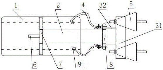
[0030] A conductor rail collector such as Figure 1~3 As shown, it is a one-phase collector in a three-phase power supply, and the three-phase structures are the same. The front end of the conductor rail collector is small, and when sliding on the conductor rail 11, it can all be on the conductor rail 11, and is suitable for vertically arranged conductor rails. The vertically arranged conductive rails are divided into upper, middle and lower rows of three conductive rails, with a spacing of about 500mm. Due to the small spacing, only the collector brush is allowed on the upper part. The connecting plate 2 is perpendicular to the conductive rail 11 to form a vertically installed conductive rail collector.

[0031] The conductor rail collector includes a collector brush 1 arranged on the conductor rail 11 and slidingly matched with the conductor rail 11, a connecting plate mechanism hinged on the collector brush 1, and a fixing frame hinged with the connecting plate mechanism a...

Embodiment 2

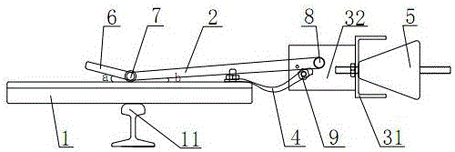
[0040] The difference between this embodiment and embodiment 1 is: as Figure 4 ~As shown in Figure 5, it is a one-phase collector in a three-phase power supply, and the three-phase structure is the same. This is a current collector on one conductive rail 11, the insulating device 5 is connected to the running equipment, and the right side of the running equipment is connected to the current collector on another conductive rail 11. Therefore, all the collectors are located above the conductive rails 11 and occupy a relatively large space, which is suitable for conductive rails arranged in a horizontal line. The connecting plate 2 is parallel to the conductive rail 11, forming a parallel-mounted conductive rail collector.

[0041] when working, such as Figure 4 or Figure 5 As shown, when the present invention slides to the left along the conductive rail 11 following the walking equipment, when a bump or rise appears on the conductive rail 11, the collector brush 1 will rot...


PUM


Abstract

The invention discloses a guide rail current collector and belongs to the technical field of track mobile device power supply apparatuses. The guide rail current collector includes a collector brush which is in sliding fit with a conductor rail, a yoke plate mechanism which is hinged to the collector brush, and a fixing rack which is hinged to the yoke plate mechanism and serves to connect a walking device. The collector brush has two ends that are along the sliding direction of the conductor rail separately provided in an oblique downward manner with a bevel [gamma] which tilts inwardly. The yoke plate mechanism includes a front pin which is hinged to the collector brush, a defining short rod which is connected to one side of the front pin in an oblique upward manner, and a yoke plate which is connected to the other side of the front pin in an oblique upward manner. The defining short rod and the yoke plate constitute an obtuse angle therebetween. The yoke plate is hinged to the fixing rack through a back pin. The collector brush and the fixing rack are connected to a braided wire for conducting electric energy therebetween. An included angle a constituted by the defining short rod and the collector brush constitute an included angle therebetween and an included angle b constituted by the yoke plate and the collector brush therebetween both range from 10 DEG to 30 DEG. According to the invention, the guide rail current collector has the characteristics of simple structure, wear resistance, long service life and deformation resistance.

Description

technical field [0001] The invention relates to a guide rail collector and belongs to the technical field of power supply devices for rail moving equipment. Background technique [0002] Collector refers to the main device that picks up electric energy on the collector side of the trolley line system. It transmits electric energy directly to the electrical appliances through the sliding of the collector brush and the guide rail, so as to realize the mobile power supply of the system. Widely used in mobile cranes, large rail locomotives, loading bridges, gantry cranes and other traveling equipment. [0003] In actual construction, since the user's slide line and track are installed in the entire workshop, there are inevitable errors in the height and distance from the track surface, which cannot be straight and horizontal. When the installation is often based on the middle, it will appear at the front and rear ends. Friction, jamming, or even damage to sliding wires and curr...

Claims


Application Information

Patent Timeline
Patent Type & Authority Applications(China)
IPC IPC(8): H01R41/00
CPCH01R41/00
Inventor 郝军峰张春峰
Owner XINXING DUCTILE IRON PIPES CO LTD
Why Eureka
Try Eureka