
Distributed Inverter Resonance Suppression Method and System Based on Capacitor Voltage Prediction

A capacitive voltage and resonance suppression technology, which is applied in the direction of electrical components, photovoltaic power generation, output power conversion devices, etc., can solve the problems of cost increase and achieve the effect of strengthening the resonance suppression effect

Active Publication Date: 2018-12-07
XUJI GRP +4
View PDF2 Cites 0 Cited by
  • Summary
  • Abstract
  • Description
  • Claims
  • Application Information

AI Technical Summary

Problems solved by technology

[0005] The purpose of the present invention is to provide a distributed inverter resonance suppression method and system based on capacitor voltage prediction to solve the problem of increasing costs caused by adding corresponding sensors in the current harmonic suppression process

Method used


Image

  • Distributed Inverter Resonance Suppression Method and System Based on Capacitor Voltage Prediction
  • Distributed Inverter Resonance Suppression Method and System Based on Capacitor Voltage Prediction
  • Distributed Inverter Resonance Suppression Method and System Based on Capacitor Voltage Prediction

Examples


Embodiment Construction

[0056] The specific embodiments of the present invention will be further described below in conjunction with the accompanying drawings.

[0057] Embodiment of Distributed Inverter Resonance Suppression Method Based on Capacitor Voltage Prediction

[0058] The present invention estimates the instantaneous value of the capacitor voltage containing the resonant component through the collected grid-side voltage and the calculated voltage drop of the parasitic resistance in the grid-side filter inductance, and uses the estimated capacitor voltage as a feedback variable by adopting an active damping control method to control the inverter. Transformer for resonance suppression.

[0059] The principle of the present invention will be described in detail below by taking a typical single-phase LCL filter as an example. The LCL filter circuit used in the photovoltaic inverter is as follows: image 3 As shown, where V is the voltage on the bridge arm side of the inverter, E is the voltag...


PUM


Abstract

The invention relates to a distributed inverter resonance suppression method and system based on capacitor voltage prediction, and belongs to the technical filed of inverter control. The distributed inverter resonance suppression method comprises the steps: according to the collected voltage on line side and the obtained voltage drop of a parasitic resistor in a filter inductor on line side through calculation, estimating the capacitor phase voltage instantaneous value containing a resonance signal component, and utilizing an active damping control method taking an estimated capacitor voltage as the feedback variable to perform resonance suppression. For further strengthen the resonance suppression effect, the distributed inverter resonance suppression method and system also integrate with a grid connection point voltage proportion control resonance suppression method, and can verify the validity of the algorithm through simulation and tests. As collection of the voltage on line side exists in an inverter original circuit, the distributed inverter resonance suppression method and system do not need increasing extra cost and only need adding the resonance suppression algorithm in the original control algorithm.

Description

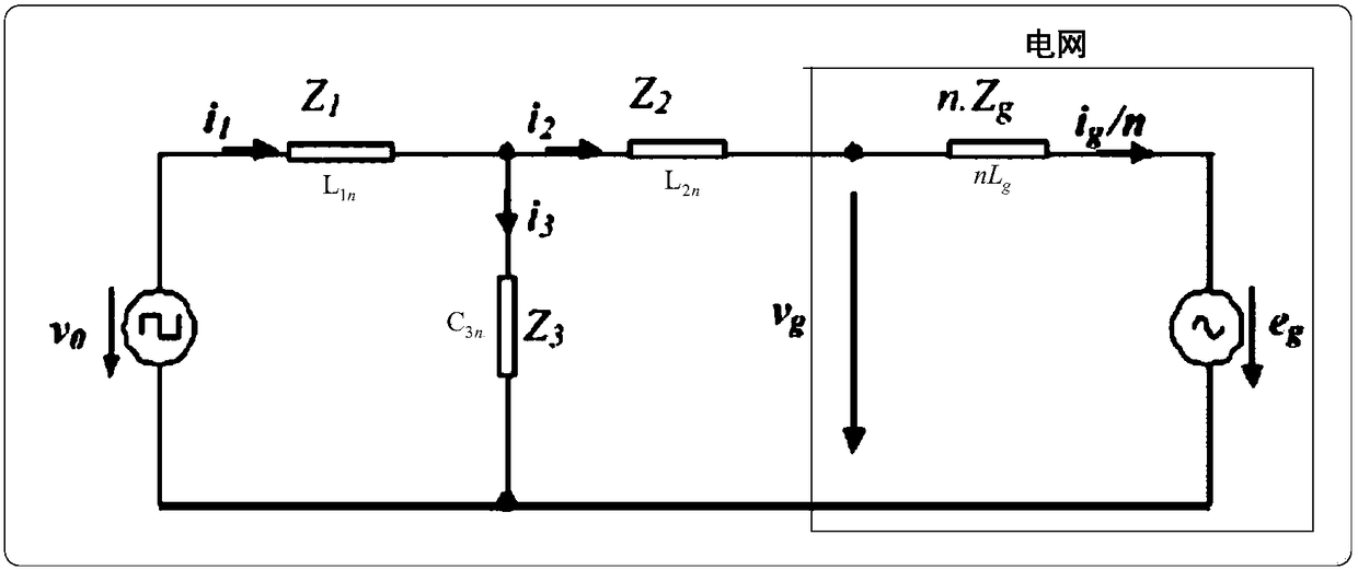
technical field [0001] The invention relates to a distributed inverter resonance suppression method and system based on capacitor voltage prediction, belonging to the technical field of inverter control. Background technique [0002] For the multi-grid-connected inverter cluster of the distributed generation system, its model and its equivalent model circuit are as follows: figure 1 As shown, it includes multiple parallel inverters. Considering that the inverters in the distributed photovoltaic cluster system usually come from the same manufacturer, the inverter LCL filter parameters, control loop parameters, digital delay, PWM time base and other parameters are exactly the same, so through simplification and combination, the equivalent model circuit diagram of the nth inverter in the distributed cluster system can be further obtained as shown in figure 2 shown. from figure 2 It can be obtained that when n inverters are connected in parallel, the resonant frequency expr...

Claims


Application Information

Patent Timeline
Patent Type & Authority Patents(China)
IPC IPC(8): H02M7/537H02M1/12
CPCY02E10/56
Inventor 曹建博张海龙王林黄辉肖飞孙健常乾坤王存平
Owner XUJI GRP
Learn More