Culture pond system realizing rotational-flow dirt collection

A breeding pond and flow collection technology, which is applied in the field of breeding pond systems, can solve the problems of large interference of aeration facilities on water flow, unfavorable water body flow and water circulation, unfavorable water discharge and circulation, etc., so as to improve the effect of sewage collection and avoid pollution. Water layer exchange, ease of difficulty and effects of water volume

Active Publication Date: 2016-08-10
FISHERY MACHINERY & INSTR RES INST CHINESE ACADEMY OF FISHERY SCI
View PDF8 Cites 17 Cited by
  • Summary
  • Abstract
  • Description
  • Claims
  • Application Information

AI Technical Summary

Problems solved by technology

[0008] The technical problem to be solved in the present invention is: in the existing swirl sewage collection pond system, since the surge machine is in operation, it is easy to cause the exchange of the upper and lower water layers, and the rising water generated by the surrounding water of the surge machine will deposit the pond The feces and residual bait at the bottom are brought back to the water body, causing secondary pollution; all the sewage is discharged from the bottom, and it is difficult to separate and purify, which brings greater pressure to the purification facility; the aeration facility interferes more with the water flow. It is not conducive to the work of water discharge and circulation; the effect of forming swirl is poor, which is not conducive to water flow and water circulation; the speed of hydrocyclone in the middle of the pond is poor, and the effect of sewage collection is poor, especially when the fish breeding density is high. When the speed of hydrocyclone is low, it is difficult to remove feces and residual bait in high-density fish culture

Method used


Image

  • Culture pond system realizing rotational-flow dirt collection
  • Culture pond system realizing rotational-flow dirt collection
  • Culture pond system realizing rotational-flow dirt collection

Examples


Embodiment Construction

[0032] The present invention will be further described below in conjunction with the accompanying drawings and specific embodiments.

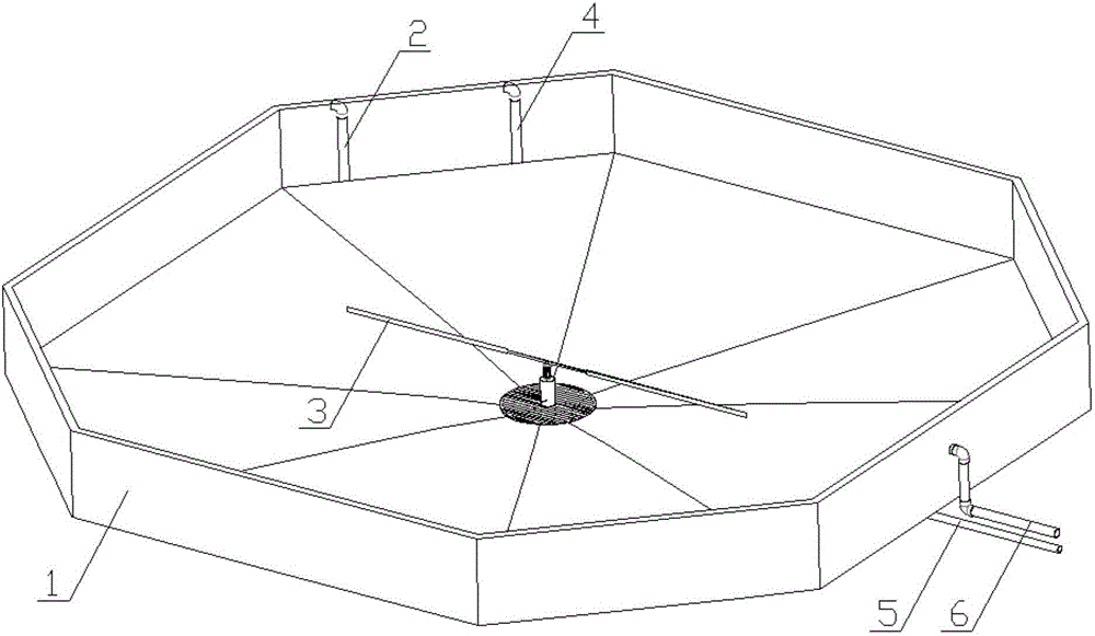
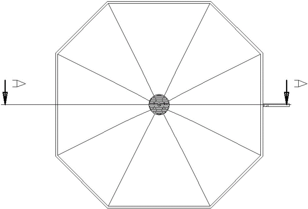
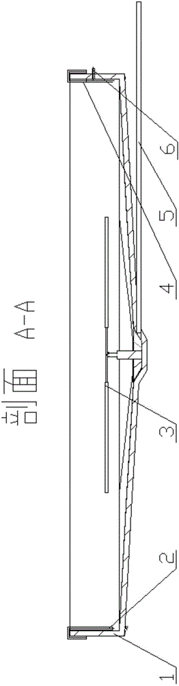
[0033] see Figure 1-Figure 4 , a culture pond system for swirl sewage collection, comprising a circular or regular polygonal pool body 1, the center of the pool body 1 has a certain taper downward; the bottom of the pool body 1 is provided with a swirl flow sewage collection device 3 , the swirling sewage collection device 3 has a motor 303, the motor 303 drives the horizontal support rod 302 to rotate, and the end of the support rod 302 is connected to the propeller 301; the direction of the swirling flow generated by the propeller 301 is vertically downward, and the propeller The distance between 301 and the bottom of the pool is less than 1 meter; a support column 304 is provided below the motor 303, and the support column 304 is fixedly connected with the dirt collection tank 305, and the dirt collection tank 305 collects fixed particles, ...


PUM


Abstract

The invention relates to a culture pond system realizing rotational-flow dirt collection. The culture pond system comprises a circular or a regularly polygonal pond body, wherein the center of the pond body is tapered downwards to a certain extent; a rotational-flow dirt-collecting device is arranged at the bottom of the pond body and is provided with a motor, the motor drives a horizontal supporting rod to rotate, and one end of the supporting rod is connected with a propeller; the distance from the propeller to the bottom of the pond body is smaller than 1 m; a supporting column is arranged below the motor and fixedly connected with a dirt collecting tank, the dirt collecting tank collects solid particles and is communicated with a bottom particle discharge pipe, and sewage is discharged out of the pond body through the bottom particle discharge pipe; a clean water discharge pipe is arranged on the side wall of the pond body, and a water inlet pipe and an aeration oxygenation pipe are arranged in positions near the side wall of the pond body; upper-layer clean water discharged through the clean water discharge pipe accounts for 80%-90% of the total amount of discharged water and flows back to the pond body through the water inlet pipe after being purified by a water purifying system; sewage discharged through the bottom particle discharge pipe accounts for 10%-20% of the total amount of discharged water.

Description

technical field [0001] The invention relates to a culture pond system for swirling sewage collection, and belongs to the technical field of culture pond systems. Background technique [0002] Industrialized aquaculture ponds have the characteristics of land saving, energy saving, high efficiency, and emission reduction. In recent years, they have developed rapidly in Jiangsu, Zhejiang, Shandong and other places in my country. At present, industrialized aquaculture ponds are generally rectangular ponds. Water enters from one side and exits from the other. In the form of push flow, more fish feces are often deposited at the bottom of the aquaculture pond, resulting in serious pollution of the aquaculture water. [0003] First of all, for sewage collection, there is a high-level pond circulating water fish farming system in the prior art, which collects sewage by swirling with a surge machine. But the system has many shortcomings in actual operation. During the operation of th...

Claims


Application Information

Patent Timeline
Patent Type & Authority Applications(China)
IPC IPC(8): A01K63/00A01K63/04
CPCA01K63/003A01K63/042A01K63/045
Inventor 程果锋刘兴国陆诗敏朱浩王建周寅顾兆俊
Owner FISHERY MACHINERY & INSTR RES INST CHINESE ACADEMY OF FISHERY SCI
Why Eureka
Try Eureka