Laser 3D forming process of cavity parts

A forming process and laser technology, applied in the improvement of process efficiency, additive processing, additive manufacturing, etc., can solve the problems of low surface accuracy of the sealing section of the part, low surface accuracy of the part forming, and difficulty in forming the part, so as to eliminate the interference phenomenon. , Good forming effect, and the effect of improving precision

Active Publication Date: 2018-12-21
SUZHOU UNIV
View PDF5 Cites 0 Cited by
  • Summary
  • Abstract
  • Description
  • Claims
  • Application Information

AI Technical Summary

Problems solved by technology

[0005] In the prior art, during the whole process of machining parts, especially in parts with small diameters, the lower end of the laser optical head or the laser beam is prone to interfere with the formed surface, resulting in difficulty in forming the parts and the surface accuracy of the formed parts. Low
In addition, for the manufacture of small and medium-sized closed cavity parts, in the sealing section, due to the serious accumulation of heat, it is easy to cause collapse, resulting in low surface accuracy of the sealing section of the part, or even complete sealing

Method used


Image

  • Laser 3D forming process of cavity parts
  • Laser 3D forming process of cavity parts

Examples


Embodiment 1

[0027] Embodiment 1: When the cavity part is not a closed cavity part, that is, when the cavity part does not need to be sealed, the cavity part laser 3D forming process includes the following steps:

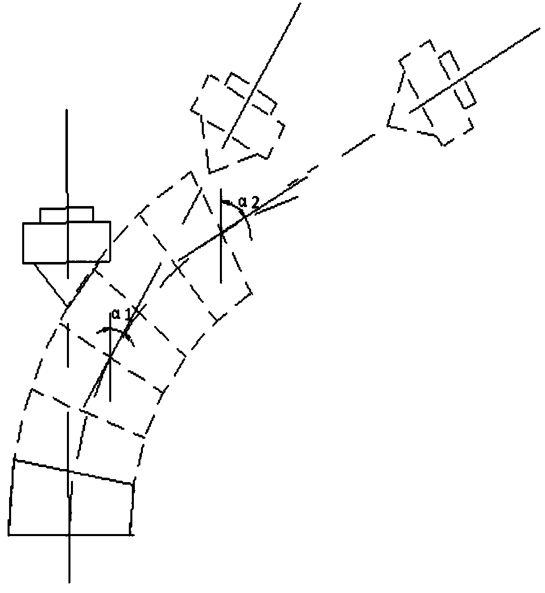
[0028] 1) Establish the three-dimensional geometric model of the cavity part; according to the calculation of whether the lower end of the laser head or the laser beam will interfere with the formed part of the cavity part, the three-dimensional model is divided into a directional forming area and a normal forming area; the lower end of the laser head Or the part where the laser beam will interfere with the formed part of the cavity part is set as the directional forming area, and the rest is the normal forming area;

[0029] 2) The laser optical head adopts the method of feeding powder in the light, and the laser optical head is a ring-conical hollow laser optical head. The laser head emits the laser beam and scans along the preset path; the laser spot combines with the metal p...

Embodiment 2

[0033] Embodiment 2: When the cavity part is a closed cavity part, the laser 3D forming process of the cavity part comprises the following steps:

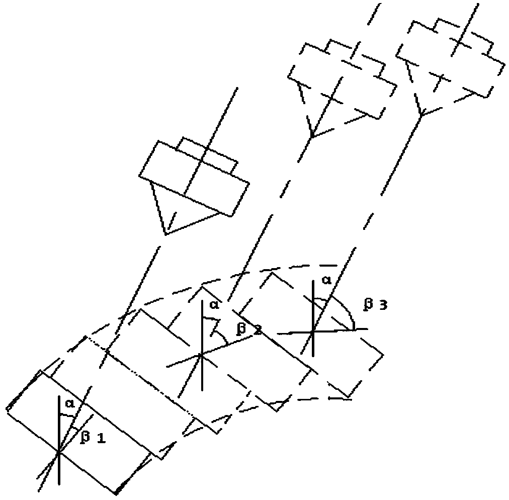
[0034] 1) Establish the three-dimensional geometric model of the cavity part; according to the calculation of whether the lower end of the laser head or the laser beam will interfere with the formed part of the cavity part, the three-dimensional model is divided into a directional forming area and a normal forming area; the lower end of the laser head Or the part where the laser beam will interfere with the formed part of the cavity part is set as the directional forming area, and the rest is the normal forming area;

[0035] 2) The laser optical head adopts the method of feeding powder in the light, and the laser optical head is a ring-conical hollow laser optical head. The laser head emits the laser beam and scans along the preset path; the laser spot combines with the metal powder sent in to complete the forming of a layer of ma...


PUM


Abstract

The invention relates to a laser 3D forming process for cavity parts, comprising the following steps: 1) establishing a geometric model of the part; dividing the model into a directional forming area and a normal forming area; the part where interference will occur is the directional forming area, and the rest are normal forming areas ;2) Outgoing laser beam, the laser spot is combined with the metal powder sent in to complete the forming of a layer of material; in the directional forming area, the axis of the bald head is scanned at a fixed angle with the vertical direction. area, the axis of the bald head is parallel to the normal of the forming surface; 3) move the bald head to the distance of a layer of material, and repeat step 2) until the processing is completed, which eliminates the interference phenomenon and obtains higher surface accuracy. When processing the sealing section of the part, the surface to be processed is divided into multiple sections along its trajectory, one section is processed, cooled for a period of time, and then the next section is processed until a layer of material is formed, which solves the problem of heat accumulation and can realize the sealing section Form normally.

Description

technical field [0001] The invention relates to a laser 3D forming process, in particular to a laser 3D forming process for cavity parts. Background technique [0002] Laser stereoforming technology is an advanced manufacturing technology formed by the combination of rapid prototyping technology and laser cladding technology. According to the different powder feeding methods, it is divided into two types, one is laser melting deposition technology, referred to as LMD technology; the other is It is selective laser melting technology, referred to as SLM technology. [0003] LMD adopts automatic powder feeding. During the processing and forming process, metal powder is synchronously injected into the molten pool from the powder storage hopper through the nozzle. Since the metal powder is dynamically ejected from the nozzle, the laser spot in LMD technology cannot be too small, otherwise most of the powder cannot be captured by the laser spot. Due to the large diameter of the ...

Claims


Application Information

Patent Timeline
Patent Type & Authority Patents(China)
IPC IPC(8): B22F3/105B22F5/10B33Y10/00
CPCB33Y10/00B22F5/10B22F10/00B22F10/36B22F10/25B22F3/105Y02P10/25
Inventor 傅戈雁方琴琴王聪石世宏邓志强周斌
Owner SUZHOU UNIV
Why Eureka
Try Eureka