Adjustable small-radius bridge girder erection machine and bridge girder erection method

A small-radius, adjustable technology, applied in the direction of erecting/assembling bridges, bridges, bridge construction, etc., to achieve the effects of easy promotion, shortened construction period, and simple operation

Active Publication Date: 2016-08-10
CHINA RAILWAY NO 2 ENG GRP CO LTD +1
View PDF6 Cites 9 Cited by
  • Summary
  • Abstract
  • Description
  • Claims
  • Application Information

AI Technical Summary

Problems solved by technology

[0004] The purpose of the present invention is: the existing bridge erecting machine existing in the prior art can only set up the larger radius flat curve bridge due to the structural limitation, and a new type of bridge erecting machine is needed to meet the needs of building highway bridges in mountainous and hilly areas. The problem encountered in the construction of small-radius flat-curve bridges is to provide an adjustable small-radius bridge erecting machine and a bridge erecting method. The bridge erecting machine is equipped with a fine-tuning mechanism to adjust the tangent between the posture of the bridge erecting machine and the curve of the small-radius bridge. Parallel to meet the erection of small-radius flat curve bridges

Method used


Image

  • Adjustable small-radius bridge girder erection machine and bridge girder erection method
  • Adjustable small-radius bridge girder erection machine and bridge girder erection method
  • Adjustable small-radius bridge girder erection machine and bridge girder erection method

Examples


Embodiment 1

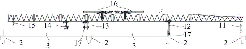
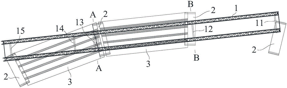
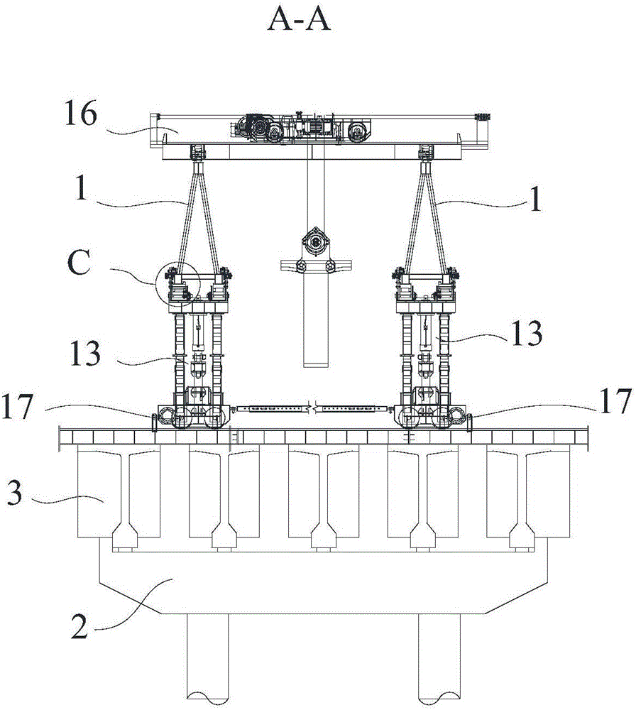
[0041] Such as Figure 1-6 As shown, an adjustable small-radius bridge erecting machine according to the present invention includes two main girders 1 arranged in parallel, and a hoisting mechanism 16 arranged between the two main girders 1 .

[0042]The bottom of each main girder 1 is also connected with support leg one 12, support leg two 13, support leg three 11 and support leg four 15, and all the bottoms of support leg one 12 and support leg two 13 are provided with several transverse The moving mechanism 17 and the top are equipped with several rollers 18, and the bottom of each said traversing mechanism 17 contacts the pier 2 or the box girder 3 and can move laterally relative to the pier 2 or the box girder 3, and each of the said rollers 18 has two Each end is provided with a limiting plate 181, and the distance between all the two opposing limiting plates 181 is adjustable. Each main beam 1 is slidably connected to all the rollers 18 on the corresponding side, and is...

Embodiment 2

[0048] Such as Figure 1-6 As shown, the bridging method of an adjustable small-radius bridge-erecting machine according to the present invention includes an adjustable small-radius bridge-erecting machine as described in Embodiment 1, and its bridging method includes the following steps:

[0049] A, normal beam erection, at this moment, the distance between all the two relative limiting plates 181 is the smallest, and the first leg 12 and the second leg 13 in the horizontal plane are all perpendicular to the main beam 1;

[0050] B. When the girder goes to the place where the small-radius flat curve bridge is erected, the distance between all the two relative limiting plates 181 is increased, and the third leg 11 and the fourth leg 15 are overhead, That is, the third leg 11 and the fourth leg 15 are raised until they leave the corresponding pier 2 or box girder 3;

[0051] C. Drive the lateral movement mechanism 17 on the second leg 13 to move laterally, so that the main bea...


PUM


Abstract

The invention discloses an adjustable small-radius bridge girder erection machine, which comprises girders and supporting legs, wherein transverse moving mechanisms are arranged at the bottom parts of the supporting legs, and roller wheels are arranged at the top parts of the supporting legs; the transverse moving mechanisms are used for transversally moving on piers or box girders in a contact way, and the two ends of the roller wheels are respectively provided with limiting plates; the distance between the two limiting plates is adjustable, and the girders are slidably connected with the roller wheels and arranged between the two limiting plates; lifting mechanisms for adjusting height are arranged on the supporting legs. By using the bridge girder erection machine, the roller wheels with adjustable limiting plate distances are arranged, and the gaps between the limiting plates and the girders are adjusted to be small, so that the girders normally move forward relative to the supporting legs when the girder erection work is conducted by the bridge girder erection machine; when steering is needed, the gaps between the limiting plates and the girders are adjusted to be maximum, and the transverse moving mechanism of one supporting leg is driven to transversally move, so that the girder makes a circular motion by taking the other supporting leg as a fulcrum to achieve that the girder attitude of the bridge girder erection machine is adjusted to be in parallel with the tangent line of the erected bridge curve and achieve the erection purpose of a small-radius horizontal curve bridge. The bridge girder erection machine has the advantages of simple structure, cost saving and shortening of construction schedule of the small-radius horizontal curve bridge.

Description

technical field [0001] The invention relates to bridge construction equipment, in particular to an adjustable small-radius bridge erecting machine and a bridge erection method. Background technique [0002] In today's bridge construction, considering the cost, construction period, construction difficulty and many other factors, the bridge erecting machine is often used for bridge construction. The bridge erecting machine is to place the prefabricated bridge box girder on the prefabricated bridge pier The equipment on the bridge can be reused, shorten the construction period of the bridge, and is widely used in bridge construction. [0003] However, when the bridge erecting machine is erecting a curved bridge, the posture of the bridge erecting machine needs to be adjusted to be parallel to the tangent line of the erected bridge curve, so that the bridge erecting machine can cross the span and reach the beam erection state. The main girder of the existing bridge erecting mach...

Claims


Application Information

Patent Timeline
Patent Type & Authority Applications(China)
IPC IPC(8): E01D21/00
CPCE01D21/00
Inventor 郑福建何开伟游义金谭祥国刘泽肖平黄钢
Owner CHINA RAILWAY NO 2 ENG GRP CO LTD
Why Eureka
Try Eureka