Urban emergency rainwater drainage system

An emergency drainage and rainwater technology, which is applied to waterway systems, sewer systems, drainage structures, etc., can solve the problems of large construction area, long period, and low frequency of use, and achieve the effect of solving rainwater deposition, simple construction, and compact design

Active Publication Date: 2016-08-10
WUXI MUNICIPAL DESIGN INST
View PDF5 Cites 2 Cited by
  • Summary
  • Abstract
  • Description
  • Claims
  • Application Information

AI Technical Summary

Problems solved by technology

[0002] With the rapid development of modern cities, the rapid increase of cement, asphalt ground and various large buildings in the city has greatly reduced the self-drainage function of the city, and the commonly used rainwater drainage system is often unable to cope with sudden sudden precipitation and Long-term precipitation during the rainy season, and if the entire urban rainwater drainage system is expanded, the cost and maintenance cost will be high, and the frequency of use will be low. At the same time, due to the large construction area and long cycle, it will bring great inconvenience to the production and life of the entire city.

Method used


Image

  • Urban emergency rainwater drainage system
  • Urban emergency rainwater drainage system
  • Urban emergency rainwater drainage system

Examples


Embodiment Construction

[0021] The present invention will be further described below in conjunction with specific drawings and embodiments.

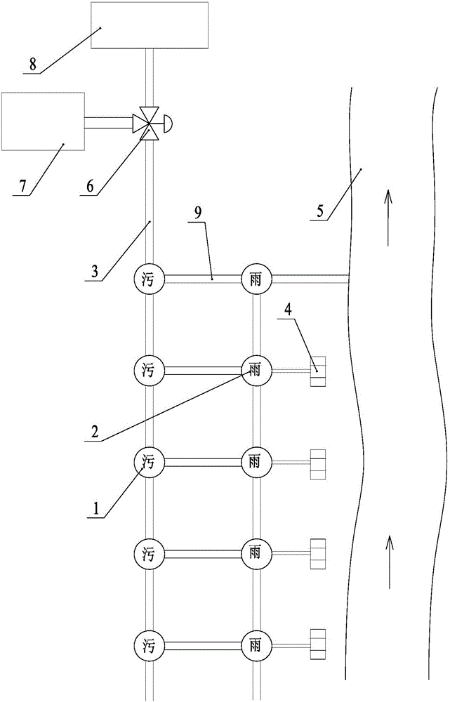
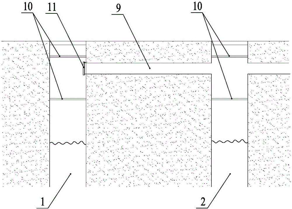
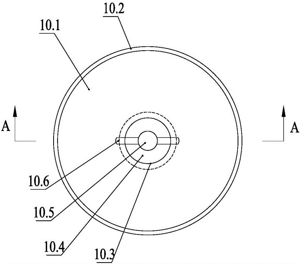
[0022] like figure 1 As shown, the urban rainwater emergency drainage system in the embodiment mainly includes a sewage well 1, a rainwater well 2 and a sewage discharge pipe 3, and the rainwater well 2 is connected to a rainwater collection well 4 and a drainage ditch 5, and the end of the sewage discharge pipe 3 Connected to the sewage treatment terminal 8, each sewage well 1 and each rainwater well 2 are equipped with upper and lower two-layer one-way anti-reverse seepage devices 10, all sewage wells 1 are connected in series or parallel to the sewage discharge pipeline 3, the main The treatment pipeline is connected to each rainwater well 2 and is communicated with the nearest sewage well 1 through a communication pipeline 9; Between the one-way anti-reverse seepage devices 10; the outlet end of the communication pipe 9 communicates with the sewage well 1,...


PUM


Abstract

The invention relates to an urban emergency rainwater drainage system, comprising drain wells, rainwater wells and a sewage discharge pipeline, wherein the rainwater wells are respectively connected with rainwater collection wells and are separately connected with a drainage ditch; the tail end of the sewage discharge pipeline is communicated with a sewage treatment terminal; the urban emergency rainwater drainage system is characterized in that each drain well is internally provided with an upper layer of one-way reverse osmosis prevention device and a lower layer of one-way reverse osmosis prevention device, and each rainwater well is internally provided with an upper layer of one-way reverse osmosis prevention device and a lower layer of one-way reverse osmosis prevention device; all the drain wells are connected in series or in parallel on the sewage discharge pipeline; a main treatment pipeline is communicated with all the rainwater wells, and all the rainwater wells are respectively communicated with the at least one drain well by a communicating pipeline; inlet ends of the communicating pipelines are communicated with the rainwater wells, and inlets of the communicating pipelines are respectively formed between the two layers of one-way reverse osmosis prevention devices on the walls of the rainwater wells; outlet ends of the communicating pipelines are communicated with the drain wells, outlets of the communicating pipelines are respectively formed between the two layers of one-way reverse osmosis prevention devices on the walls of the drain wells, and one-way communicating vessels are respectively installed at the outlets of the communicating pipelines. The urban emergency rainwater drainage system is simple in structure, compact in design, simple and convenient in construction, energy-saving and environment-friendly, and can effectively solve the problem of rain deposition while effectively utilizing the available resources.

Description

technical field [0001] The invention and an urban rainwater emergency drainage system belong to the technical field of municipal pipe network facilities. Background technique [0002] With the rapid development of modern cities, the rapid increase of cement, asphalt ground and various large buildings in the city has greatly reduced the self-drainage function of the city, and the commonly used rainwater drainage system is often unable to cope with sudden sudden precipitation and Long-term precipitation during the rainy season, and if the entire urban rainwater drainage system is expanded, the cost and maintenance cost will be high, and the frequency of use will be low. At the same time, due to the large construction area and long cycle, it will bring great inconvenience to the production and life of the entire city. . Contents of the invention [0003] The purpose of the present invention is to overcome the deficiencies in the prior art, and provide an urban rainwater emer...

Claims


Application Information

Patent Timeline
Patent Type & Authority Applications(China)
IPC IPC(8): E03F1/00E03F3/02E03F5/04E02D29/14C02F9/06C02F101/20
CPCY02W10/37E03F1/00C02F1/001C02F1/281C02F1/283C02F1/46104C02F9/00C02F2101/20E02D29/14E03F3/02E03F5/04
Inventor 祝启祥史晓忠刘杰储友兵
Owner WUXI MUNICIPAL DESIGN INST
Why Eureka
Try Eureka