A space truss beam

A space truss and diagonal rib technology, applied in the field of space truss beams, can solve the problems of unreachable local bearing capacity, low buckling resistance of webs, and reduced web bearing capacity, etc., and achieve good local stability, engineering design and construction. Simple and effective in reducing project cost

Active Publication Date: 2018-02-09
张波
View PDF7 Cites 0 Cited by
  • Summary
  • Abstract
  • Description
  • Claims
  • Application Information

AI Technical Summary

Problems solved by technology

In the long-term application, it is found that the disadvantage of this kind of H-shaped steel load-bearing beam is: the buckling resistance of the web of H-shaped steel is low, limited by the height and thickness ratio, when a large shear capacity, flexural capacity or When higher stability is required, the thickness of the web must be increased. However, the result of increasing the thickness of the web is that the amount of steel used is increased, and the weight is greatly increased. In particular, the local bearing capacity cannot meet the same requirements, and other components are needed in engineering applications. Cooperate, the method of opening holes on the web to pass through the pipeline will easily reduce the bearing capacity of the web and increase the construction cost; when anchoring with concrete, the placement position of the steel bar needs to be strictly designed, and the design and construction are relatively high.

Method used


Image

  • A space truss beam
  • A space truss beam
  • A space truss beam

Examples


Embodiment Construction

[0007] The present invention will be further described with reference to the accompanying drawings.

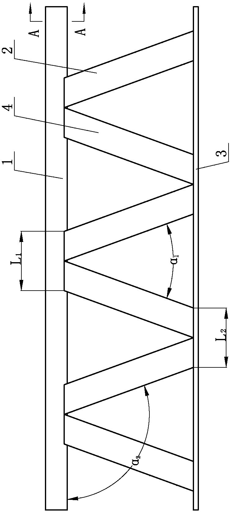
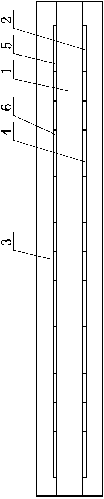
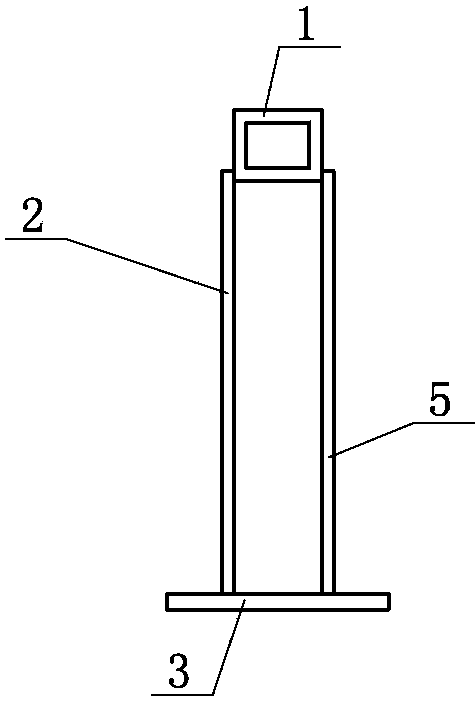
[0008] A space truss beam of the present invention comprises an upper wing bar 1 and a lower wing plate 3, the upper wing bar 1 and the lower wing plate 3 are parallel, and several first diagonal ribs 2 are connected between the upper wing bar 1 and the lower wing plate 3 , several second oblique ribs 4, several third oblique ribs 5 and several fourth oblique ribs 6, the lengths of each oblique ribs are equal, and several first oblique ribs 2 and several second oblique ribs 4 are located on the upper wing 1 on one side in the width direction, several third diagonal ribs 5 and several fourth diagonal ribs 6 are located on the other side of the upper wing bar 1 in the width direction, and a first clip is arranged between the first diagonal rib 2 and the second diagonal rib 4 Angle α 1 , the third angle α is set between the third oblique helper 5 and the fourth oblique rib 6 3 ...


PUM


Abstract

The invention provides a space truss girder, comprising an upper wing rod and a lower wing plate, wherein the upper wing rod is parallel to the lower wing plate; a plurality of first diagonal ribs, a plurality of second diagonal ribs, a plurality of third diagonal ribs and a plurality of fourth ribs are arranged between and connected with the upper wing rod and the lower wing plate; the lengths of all the diagonal ribs are equal; the plurality of first diagonal ribs and the plurality of second diagonal ribs are located at one side of the width direction of the upper wing rod; the plurality of third diagonal ribs and the plurality of fourth ribs are located at the other side of the width direction of the upper wing rod; first included angles alpha 1 are arranged between the first diagonal ribs and the second diagonal ribs; third included angles alpha 3 are arranged between the third diagonal ribs and the fourth diagonal ribs; and the first included angles alpha 1 and third included angles alpha 3 are acute angles. The torsional capacity, shear capacity and flexural capacity of the space truss girder provided by the invention are 40-60%, 20-30% and 40-60% higher compared with the prior art; in usage of space truss girder, additional arrangement of ribs with torsional capacity or bracing frames, or any other structures are not needed; and the space truss girder is simple in engineering design and construction and greatly reduces cost.

Description

technical field [0001] The invention relates to a construction engineering component, which is a space truss beam. Background technique [0002] Among the steel structures widely used in construction engineering, H-shaped steel is the main form of load-bearing beams. Usually, the height of the storey is increased, holes are opened on the web, ribs are added by welding, and support frames are set according to the requirements of use. In the long-term application, it is found that the disadvantage of this kind of H-shaped steel load-bearing beam is: the buckling resistance of the web of H-shaped steel is low, limited by the height and thickness ratio, when a large shear capacity, flexural capacity or When higher stability is required, the thickness of the web must be increased. However, the result of increasing the thickness of the web is that the amount of steel used is increased, and the weight is greatly increased. In particular, the local bearing capacity cannot meet the s...

Claims


Application Information

Patent Timeline
Patent Type & Authority Patents(China)
IPC IPC(8): E04C3/08
CPCE04C3/08
Inventor 张波张树辉
Owner 张波
Why Eureka
Try Eureka