
Ball seat assembly and ball-pitching sliding sleeve type fracturing device

A sliding-sleeve, fracturing technology that is applied to wellbore/well valve devices, wellbore/well components, production fluids, etc., and can solve problems such as difficulty of impact, high perforation cost, and long drilling time , to avoid damage to the ground, improve the degree of automation, and reduce construction costs

Active Publication Date: 2016-08-10
PETRO KING ENERGY TECH HUIZHOU CO LTD
View PDF10 Cites 12 Cited by
  • Summary
  • Abstract
  • Description
  • Claims
  • Application Information

AI Technical Summary

Problems solved by technology

[0003] When the construction method of cable perforation combined with composite bridge plug is used, the cost of perforation is high, and perforation may cause damage to the formation; pumping the bridge plug requires a lot of water; the drilling cost is high and the drilling time is long
Moreover, after working for a certain distance, it is necessary to take out the cable to replace the bridge plug and perforating bullets, and the construction period is quite long; during the construction process, a cable car needs to be used
In addition, the approval and transportation of perforating bullets, setting tools and gunpowder are very difficult, which will affect the construction efficiency
[0004] When using the construction method of packer and fracturing sliding sleeve, it is necessary to stop the pump to throw and send the ball during operation, and it is necessary to drill or salvage the ball seat after the operation is completed; due to the structure of the fracturing sliding sleeve itself, the section Hierarchical levels are limited
In addition, the drilling and grinding quality of the ball seat will directly affect the difficulty of subsequent repeated reconstruction
[0005] When the coiled tubing belt bottom seal dragging technology is used, the cost of perforation is high, which may cause damage to the coiled tubing; it is limited by the length of the coiled tubing, and the cost of the coiled tubing vehicle is also high
In addition, this construction method will also face the risk of sand jams

Method used


Image

  • Ball seat assembly and ball-pitching sliding sleeve type fracturing device
  • Ball seat assembly and ball-pitching sliding sleeve type fracturing device
  • Ball seat assembly and ball-pitching sliding sleeve type fracturing device

Examples


Embodiment Construction

[0052] In order to make the object, technical solution and advantages of the present invention clearer, the present invention will be further described in detail below in conjunction with the accompanying drawings and embodiments. It should be understood that the specific embodiments described here are only used to explain the present invention, not to limit the present invention.

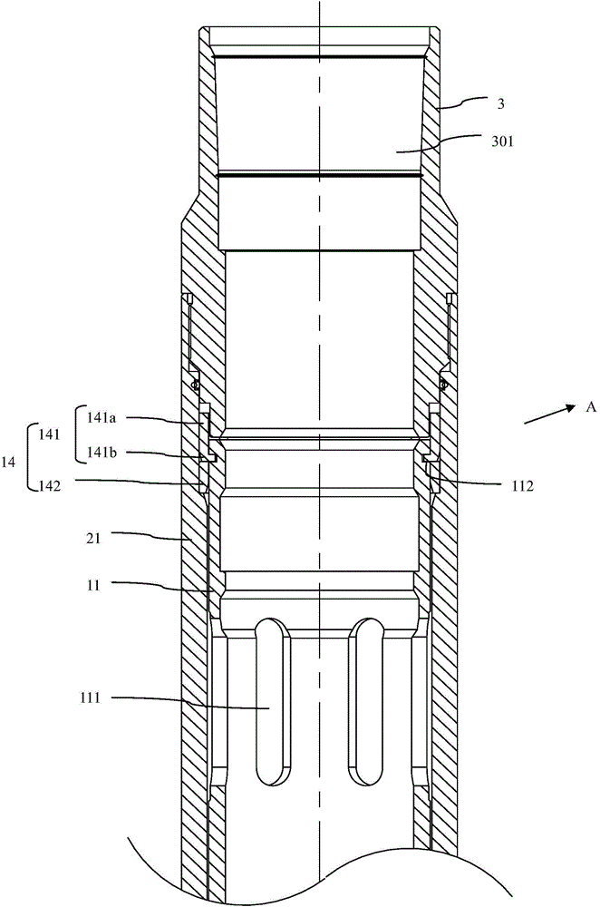
[0053] figure 1 A schematic structural view of a ball-sleeve type fracturing device in a specific embodiment of the present invention is shown. In order to show the details of the ball-sliding sleeve type fracturing device more clearly, it is divided into four sections A, B, C and D along the axial direction for further description. For details, see figure 2 , image 3 , Figure 7 and Figure 13 .

[0054] The fracturing device includes an inner sleeve 1, an outer sleeve 2, an upper joint 3, a lower joint 4, a fracturing ball 5, a ball seat assembly 6 and a spring 9, and the inner sleeve 1 an...


PUM


Abstract

The invention relates to a ball seat assembly and a ball-pitching sliding sleeve type fracturing device. The ball-pitching sliding sleeve type fracturing device comprises an inner sleeve, and outer sleeve, a fracturing ball, and the ball seat assembly. The inner sleeve is slidably sleeved in the outer sleeve. The inner sleeve and the outer sleeve are respectively provided with fracturing windows. The inner sleeve slides to open or close the fracturing window. The inner side surface of the outer sleeve is provided with a fracturing ball releasing groove. The fracturing ball is pitched on the ball seat assembly. When the ball seat assembly moves to the fracturing ball releasing groove, the fracturing ball generates thrust under the action of external forces, to push a plurality of ball seat supports to move outward along a radial direction, and the fracturing ball passes through the ball seat assembly and falls into a next section of the ball-pitching sliding sleeve type fracturing device. Using the ball-pitching sliding sleeve type fracturing device can realize an objective of fracturing an infinite layer section by just pitching a ball, and construction cost is reduced and yield of a single well is increased. The device solves defects in the prior art of range limitation of a fracturing sliding sleeve and influence of sliding of the inner sleeve after a shear pin is cut off.

Description

technical field [0001] The invention relates to the field of oil and gas well completion equipment, in particular to a ball seat assembly and a ball-throwing sliding sleeve type fracturing device. Background technique [0002] In the prior art, the construction technology for the reconstruction of shale gas reservoirs and low-permeability reservoirs usually uses cable-transmitted perforating guns with composite bridge plugs, or packers with fracturing sleeves, or coiled tubing with bottom seals. However, these existing construction techniques have certain limitations. [0003] When the construction method of cable perforation combined with composite bridge plug is used, the perforation cost is high, and the perforation may cause damage to the formation; pumping the bridge plug requires a lot of water; the cost of drilling is high, and the drilling time is long. Moreover, after working for a certain distance, it is necessary to take out the cables to replace the bridge plugs...

Claims


Application Information

Patent Timeline
Patent Type & Authority Applications(China)
IPC IPC(8): E21B43/26
CPCE21B43/12E21B34/142
Inventor 赵锦栋张曦予王昕宇李良辉黄会方郭海辉任永生李勇林清沿杨帆
Owner PETRO KING ENERGY TECH HUIZHOU CO LTD
Learn More