
A three-stable switching valve

A switching valve and tri-stable technology, applied in the field of sanitary ware, can solve the problems that cannot be maintained, the switching mechanism is difficult to meet the use requirements, and the structure of the switching mechanism is complex, etc. It achieves low assembly difficulty, convenient user selection, and wide application range Effect

Active Publication Date: 2018-07-31
FUJIAN XIHE SANITARY WARE TECH
View PDF7 Cites 0 Cited by
  • Summary
  • Abstract
  • Description
  • Claims
  • Application Information

AI Technical Summary

Problems solved by technology

[0002] At present, most of the existing tri-stable switching valves use electronically controlled tri-stable switching mechanisms, specifically: switching by means of electric control, and relying on electromagnetic coils to maintain the switching position; for example, the patent number is: 200920071370.9, published The patent titled "A Tri-stable Solenoid Valve" published on February 17, 2010, realizes the structure of maintaining the stable position through the holding coil structure in the solenoid valve after it is energized; It can only be used after the process. For the energy-saving and environmental protection goals advocated now, that is, power supply through hydropower generation, it is difficult to achieve maintenance after switching; in addition, the existing switching mechanism structure is too complicated, and generally only one or two are considered. The switching position, that is, the switching between the switching position and the reset position, such as the switching structure of a ballpoint pen, but it can only achieve two logical switching states, and can only realize two functions; in summary, the existing switching mechanism is difficult to meet the existing use requirements

Method used


Image

  • A three-stable switching valve
  • A three-stable switching valve
  • A three-stable switching valve

Examples


specific Embodiment approach

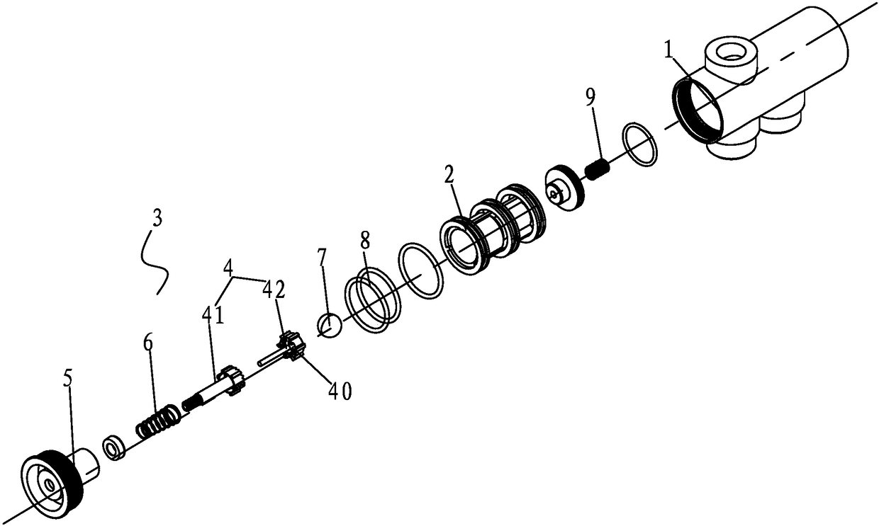
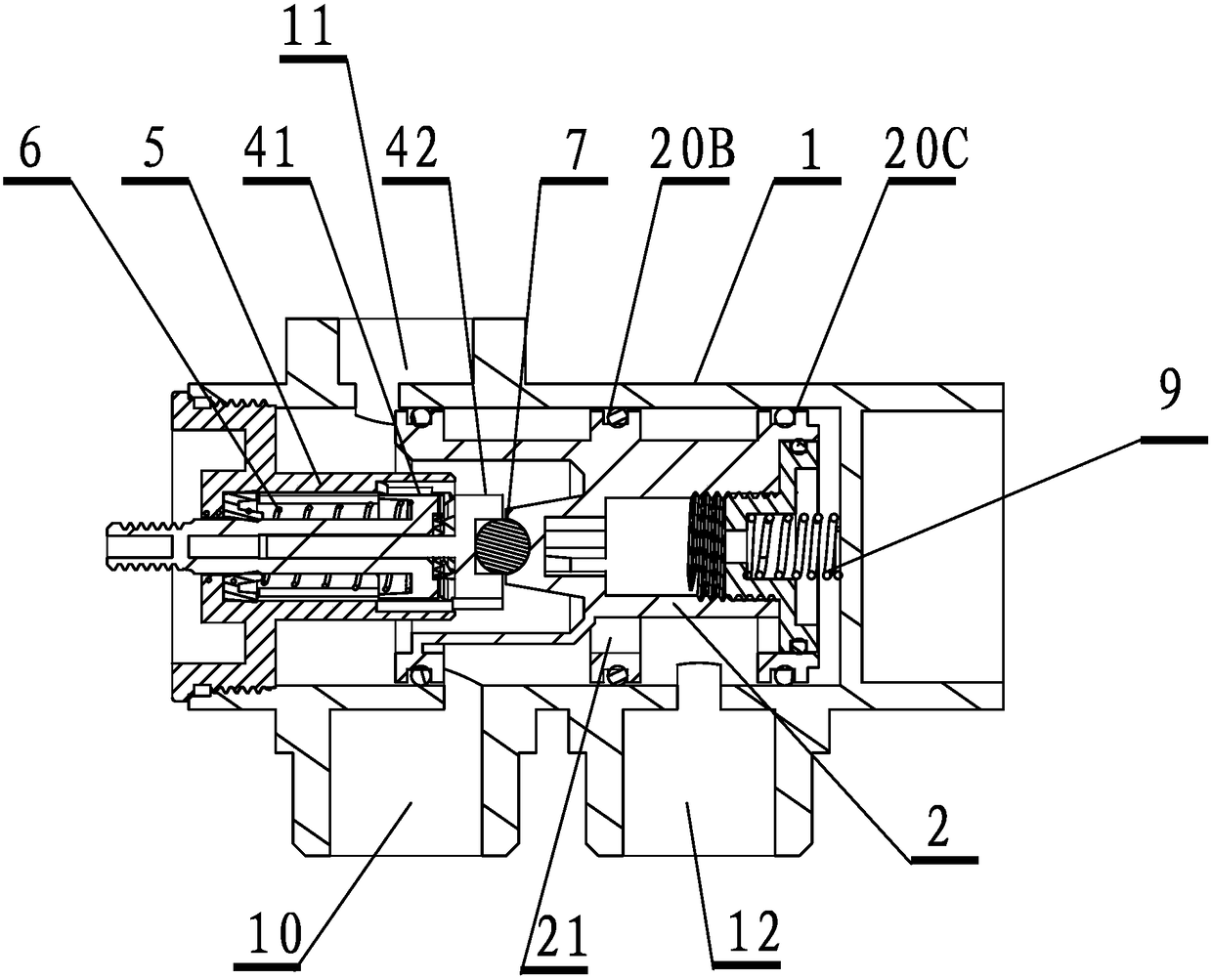
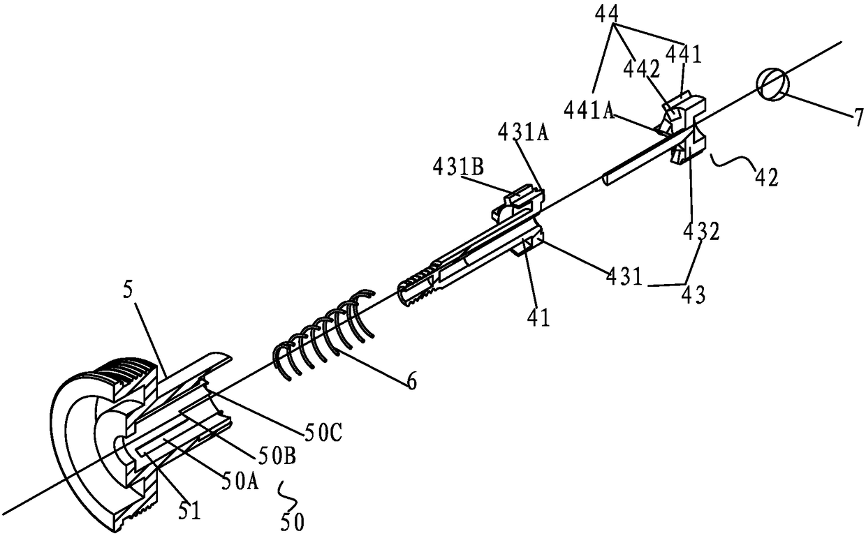
[0042] Specific implementation methods, (such as Figure 1 to Figure 10 As shown) a tri-stable switching valve according to the present invention mainly includes the following components: a housing 1, a water diversion shuttle 2, a push push piece 41, a rotating hook 42, a limit seat 5, and a preload spring 6. Adjusting beads 7, seals 8 and return springs 9;

[0043] During actual assembly, the water diversion part: the housing 1 is provided with a water inlet 10 and at least two water outlets 11, 12; 9 is installed at the end of the water diversion shuttle 2, and then the water diversion shuttle 2 is placed in the housing 1 and corresponds to the position of the water inlet and outlet 11 and 12;

[0044] Part 3 of the press switching assembly: including the push push piece 41, the rotary hook 42, the limit seat 5 and the pre-tension spring 6; the limit seat 5 has at least three stop parts 50; the press drive unit 4 has a connecting portion 40 that matches the stop portion 5...


PUM


Abstract

The invention discloses a three-stable state switching valve. The three-stable state switching valve comprises a shell; the shell is provided with a water inlet and at least two water outlets. The three-stable state switching valve further comprises a water diversion shuttle used for switching water diversion and a pressing switching assembly provided with at least three stop parts; the water diversion shuttle is installed inside the shell and is provided with water sealing parts corresponding to the stop parts; the water sealing parts are matched with the water outlets in a switching mode so that any water outlet can output water; the pressing switching assembly is matched with the water diversion shuttle, drives the water diversion shuttle to move and comprises a pressing drive unit, a limiting base and a preloaded spring, the limiting base is provided with at least three stop parts, the pressing drive unit is provided with connection parts matched with the stop parts, and the preloaded spring acts on the part between the pressing drive unit and the limiting base. According to the three-stable state switching valve, the pressing drive unit is matched with three or more stop parts on the limiting base, and therefore the water diversion shuttle matched with the pressing drive unit can have at least three switching modes.

Description

technical field [0001] The invention relates to the bathroom industry, in particular to a three-stable switching valve. Background technique [0002] At present, most of the existing tri-stable switching valves use electronically controlled tri-stable switching mechanisms, specifically: switching by means of electric control, and relying on electromagnetic coils to maintain the switching position; for example, the patent number is: 200920071370.9, published The patent titled "A Tri-stable Solenoid Valve" published on February 17, 2010, realizes the structure of maintaining the stable position through the holding coil structure in the solenoid valve after it is energized; It can only be used after the process. For the energy-saving and environmental protection goals advocated now, that is, power supply through hydropower generation, it is difficult to achieve maintenance after switching; in addition, the existing switching mechanism structure is too complicated, and generally...

Claims


Application Information

Patent Timeline
Patent Type & Authority Patents(China)
IPC IPC(8): F16K11/065F16K31/60F16K27/04
CPCF16K11/065F16K27/04F16K31/60
Inventor 林孝发林孝山李帅宇刘启乔邓小清
Owner FUJIAN XIHE SANITARY WARE TECH
Learn More