
Liquid stratified sampling device and stratified sampling method for liquid

A sampling device and liquid technology, applied to the sampling device and other directions, can solve the problems of inconvenient portability and storage, low degree of automation, and small sampling range, and achieve the effects of easy portability and storage, high degree of automation, and large sampling range.

Active Publication Date: 2016-08-10
SHANDONG LUKANG ZHONGHE ENVIRONMENTAL PROTECTION TECH
View PDF6 Cites 9 Cited by
  • Summary
  • Abstract
  • Description
  • Claims
  • Application Information

AI Technical Summary

Problems solved by technology

The traditional layered sampling method for liquids is to use hanging buckets for sampling, that is, tie a rope to the bucket and sink the bucket into the liquid to a specified depth for sampling. The sampling accuracy of this method is difficult to guarantee
The utility model patent with the authorized announcement number CN201212861Y discloses a miniature quantitative layered sampler. Although the sampling accuracy is improved, it has the following disadvantages: (1) Each layer of liquid needs to be extracted one by one, and the operation is complicated; (2) In order to meet the Deep sampling requires a long sampling pole, which is not easy to carry and store; (3) The process of taking samples and injecting samples prevents the samples from maintaining their original underwater state, which affects the observation effect; (4) For the samples that are far from the shore The liquid cannot be sampled, and the sampling range is small; (5) The positioning of the sampling point is not accurate, which affects the sampling accuracy; (6) The degree of automation is low

Method used


Image

  • Liquid stratified sampling device and stratified sampling method for liquid
  • Liquid stratified sampling device and stratified sampling method for liquid
  • Liquid stratified sampling device and stratified sampling method for liquid

Examples


Embodiment Construction

[0029] In order to clearly illustrate the technical features of this solution, the specific implementation of the present invention will be further described below according to the accompanying drawings.

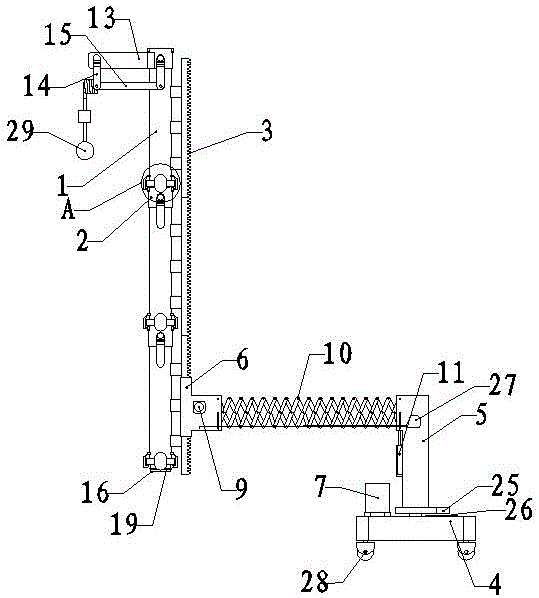
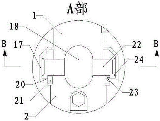
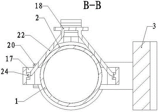
[0030] As shown in the figure, a liquid stratified sampling device includes a sampling tube and a sampling holder.

[0031] The sampling tube is composed of three sampling tube units connected end to end. The sampling tube unit includes a tube body 1, a stop valve 2 and a rack 3. The tube body 1 is made of transparent material. Scale marks set in the axial direction (not shown in the figure); the lower end of the shut-off valve 2 is connected to the upper end of the pipe body 1 through a sealed pipe thread, and the lower end of the pipe body 1 and the upper end of the shut-off valve 2 are provided with a matching sealing connection mechanism, The sealing connection mechanism includes an insertion part 16, an elastic clamping arm 17 and an unlocking button 18; the insertion p...


PUM


Abstract

The invention relates to the technical field of sample collecting devices, in particular to a liquid stratified sampling device .The device comprises a sampling tube and a sampling support .The sampling tube is formed by connecting a plurality of sampling tube units end to end .Each sampling tube unit comprises a tube body, a stop valve and a rack .The lower end of each stop valve is in sealed fixed connection with the upper end of the corresponding tube body .Matched sealed connection mechanisms are arranged at the lower end of each tube body and the upper end of the corresponding stop valve .The uppermost stop valve is provided with a stop valve switching device .The sampling support comprises a base plate, a longitudinal beam and a guide rail .The longitudinal beam is rotationally mounted on the base plate, the base plate is provided with a first motor for driving the longitudinal beam to rotate, an electric telescopic device is arranged between the guide rail and the longitudinal beam, a gear and a second motor for driving the gear to rotate are mounted on the guide rail, and the rack can slide perpendicularly along the guide rail and is engaged with the gear .The liquid stratified sampling device is high in sampling precision, large in sampling range, easy and convenient to operate, high in automation degree and easy to carry, and the original state of a sample can be observed visually.

Description

technical field [0001] The invention relates to the technical field of sample collection devices, in particular to a liquid layered sampling device and a method for liquid layered sampling. Background technique [0002] In the fields of environmental protection and tap water production, it is necessary to conduct stratified sampling and observation of water quality. For example, in the reaction sedimentation tank in the field of environmental protection, the demulsifier is used to separate the oil in the wastewater, and the sedimentation is used to make the suspended matter in the wastewater settle to the bottom layer. Sampling and observation, in order to timely adjust the demulsifier dosage, waste water flow, flow rate and other parameters of the reaction sedimentation tank. The traditional layered sampling method of liquid is to use hanging bucket to put rope to sample, that is, tie a rope to the bucket and sink the bucket into the liquid to a specified depth for samplin...

Claims


Application Information

Patent Timeline
IPC IPC(8): G01N1/16
CPCG01N1/16
Inventor 朱怀新孟良刘培臣曹莉萍
Owner SHANDONG LUKANG ZHONGHE ENVIRONMENTAL PROTECTION TECH
Learn More