System for testing damage threshold of optical element surface and test method

A surface damage and optical component technology, applied in the field of optical inspection, can solve the problems of reducing damage correlation, inaccurate description of defect damage threshold, inaccurate test results, etc.

Pending Publication Date: 2016-08-10
LASER FUSION RES CENT CHINA ACAD OF ENG PHYSICS
View PDF0 Cites 9 Cited by
  • Summary
  • Abstract
  • Description
  • Claims
  • Application Information

AI Technical Summary

Problems solved by technology

However, this test method still cannot accurately describe the damage threshold of defects, and the shortcomings are mainly manifested in:
[0005] 1. The size of the initial damage point on the surface of the component is usually 10 μm to 50 μm, and the area of ​​the test spot is usually on the order of millimeters, which is much larger than the area of ​​the damage point. The calculation of the average flux of the entire spot causes a decrease in accuracy
[0006] 2. The laser spot used in the damage threshold test is usually a Gaussian spot and a flat-top spot. The intensity distribution of the Gaussian spot is strong in the middle and weak on both sides, while the intensity distribution of the flat-top spot is uneven. The average flux and peak flux of the two kinds of spots There is a large difference in the amount, resulting in inaccurate test results
[0007] 3. The direct cause of the surface damage of optical components is that the local flux around the defect exceeds the damage threshold of the defect. Under laser irradiation, the defect is damaged to form a damage point, while other areas of the laser spot do not cause damage, and the entire spot is calculated. The light intensity reduces the correlation with damage
[0008] 4. The damage threshold of different types of defects is not the same. The existing damage testing technology cannot avoid the damage of low-threshold defects in high-flux laser irradiation. The damage threshold of the test shows that the damage threshold of the defect is not higher than the test laser flux
There is a certain deviation between the test result and the real damage threshold of the defect, which makes the test result inaccurate
[0009] Therefore, the existing damage threshold detection system and test method are difficult to guarantee the accuracy and accuracy of the damage threshold test of optical components, and it is urgent to invent a more accurate test method and test system to characterize the damage of optical components and accurately reflect the damage of optical components. The laser flux suffered when it occurs, improves the accuracy of the damage threshold test, and realizes the accurate test of the damage threshold of the local area of ​​​​the surface defect of the optical component. The results are of great significance for evaluating the quality of the optical component

Method used


Image

  • System for testing damage threshold of optical element surface and test method
  • System for testing damage threshold of optical element surface and test method
  • System for testing damage threshold of optical element surface and test method

Examples


Embodiment 1

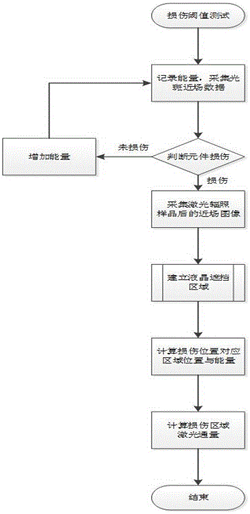
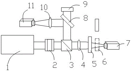
[0069] Such as figure 1 and 2 As shown, the present embodiment provides a damage threshold testing system for the surface of an optical element. The high-energy laser (wavelength 351 nm, pulse width 5 ns) emitted by the laser 1 is converged by the laser after being shaped by the liquid crystal light valve 2 through the lens 4. After reaching the surface of the sample 5 to be measured, it enters the absorption trap 6; at the same time, the laser light reflected by the beam splitter 3 is collected and collected by the mirror 8. The laser light reflected by the mirror 8 is converged to the monitoring CCD 11 through the lens 10, and the transmitted laser light enters the energy card meter 9, and is collected through the second lens. 10 converged laser spot near field, record and monitor CCD11 data, and record card meter 9 energy data.

[0070] According to the R-on-1 damage threshold test process, the laser energy was increased in steps of fixed energy until damage points appeare...


PUM

PropertyMeasurementUnit
diameteraaaaaaaaaa

Abstract

The invention discloses an optical element surface damage threshold testing system and a testing method thereof, relating to the field of optical testing, comprising a laser, a liquid crystal light valve, a beam splitter, a lens 1, a test sample, an absorption trap, a direct Depending on the CCD, reflector, energy card meter, lens two and monitoring CCD, the damage threshold testing method of the present invention is to obtain the transfer function by establishing the mapping relationship between the liquid crystal light valve and the near field of the light spot, and bring the coordinates of the damage point in the light spot into the transfer function. The function determines the occlusion area of ​​the liquid crystal light valve. When the occlusion area covers the damage point, the local flux is calculated to improve the calculation accuracy of the damage threshold.

Description

technical field [0001] The invention belongs to the field of optical detection, and in particular relates to an optical component surface damage threshold testing system and a testing method thereof. Background technique [0002] At present, the laser damage threshold detection of optical components is mainly to test the irreversible damage to the surface of optical components caused by surface defects of optical components under strong laser irradiation. Surface defects of optical components mainly refer to structural defects and defects introduced by grinding and other processing processes. Residual impurity elements will cause damage to the surface of optical components when irradiated with laser light. The damage threshold detection is mainly to detect the damage threshold caused by defects. [0003] However, the existing damage threshold testing methods usually calculate the average flux in the laser spot as the damage threshold. Due to the difference in the distributio...

Claims


Application Information

Patent Timeline
Patent Type & Authority Applications(China)
IPC IPC(8): G01N21/88
CPCG01N21/8806
Inventor 周信达丁磊郑垠波巴荣声袁静姜宏振徐宏磊张霖李东杨一杨晓瑜陈波柴立群郑万国
Owner LASER FUSION RES CENT CHINA ACAD OF ENG PHYSICS
Why Eureka
Try Eureka