
Intelligent encoding method for hydropower station equipment

A coding method and technology of hydropower stations, applied in the field of power generation equipment management, can solve problems such as time-consuming, labor-intensive, heavy workload, and inconvenient use, and achieve the effects of reducing manual intervention, improving efficiency, and ensuring uniformity

Inactive Publication Date: 2016-08-10
CHANGJIANG SURVEY PLANNING DESIGN & RES
View PDF4 Cites 10 Cited by
  • Summary
  • Abstract
  • Description
  • Claims
  • Application Information

AI Technical Summary

Problems solved by technology

The current coding method is mainly manually compiled one by one, which has the following disadvantages: (1) During the coding process, it is necessary to continuously check the manual to determine the codes corresponding to different devices and different systems, and then code and number the devices, which takes a long time and has a low accuracy rate; (2) After the coding is completed, it is necessary to manually mark the codes in the corresponding system diagram one by one. For a system containing a large number of devices, it is necessary to find out the codes from thousands of codes and mark them in the corresponding positions of the system diagram. (3) After the initial coding is completed, if there is a partial change in the system design and some equipment needs to be inserted or deleted, the coding of the entire system after the changed part needs to be recoded, which is equivalent to manual coding. The recoding of the system is time-consuming and laborious; (4) The manually compiled code is relatively independent of the data in the equipment information management system, and it needs to be manually converted to the equipment management platform, which is inconvenient to use

Method used


Image

  • Intelligent encoding method for hydropower station equipment
  • Intelligent encoding method for hydropower station equipment
  • Intelligent encoding method for hydropower station equipment

Examples


Embodiment Construction

[0043] The present invention will be further described in detail below in conjunction with the accompanying drawings and specific embodiments.

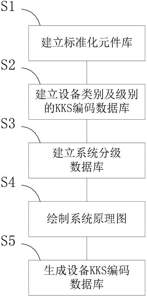
[0044] For the intelligent coding method of hydropower station equipment disclosed in this embodiment, refer to figure 1 As shown, the intelligent coding method for hydropower station equipment mainly includes the following steps:

[0045] S1: Establish a standardized component library, each component in the library has specific information. Please refer to Figure 5 As shown, it is a schematic structural diagram of the properties of gate valve components in the valve class in the component library of an embodiment of the present invention, including category, name, specification and pressure; Image 6 Shown is a schematic representation of the properties of ball valve components in valves in an embodiment of the present invention, including category, name, specification and pressure; Figure 7 Shown is a schematic representation o...


PUM


Abstract

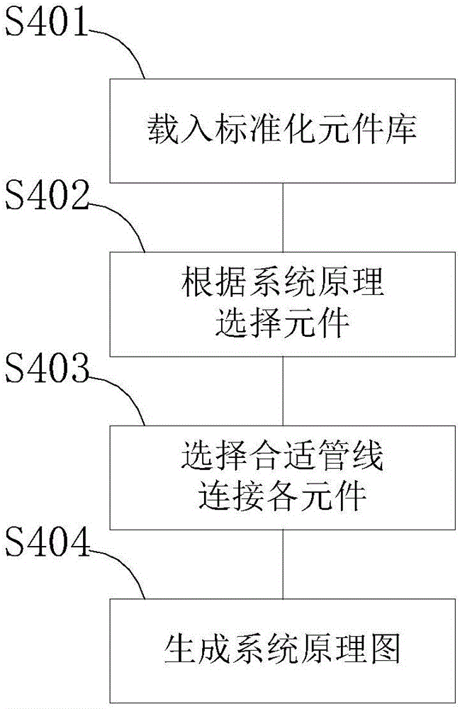
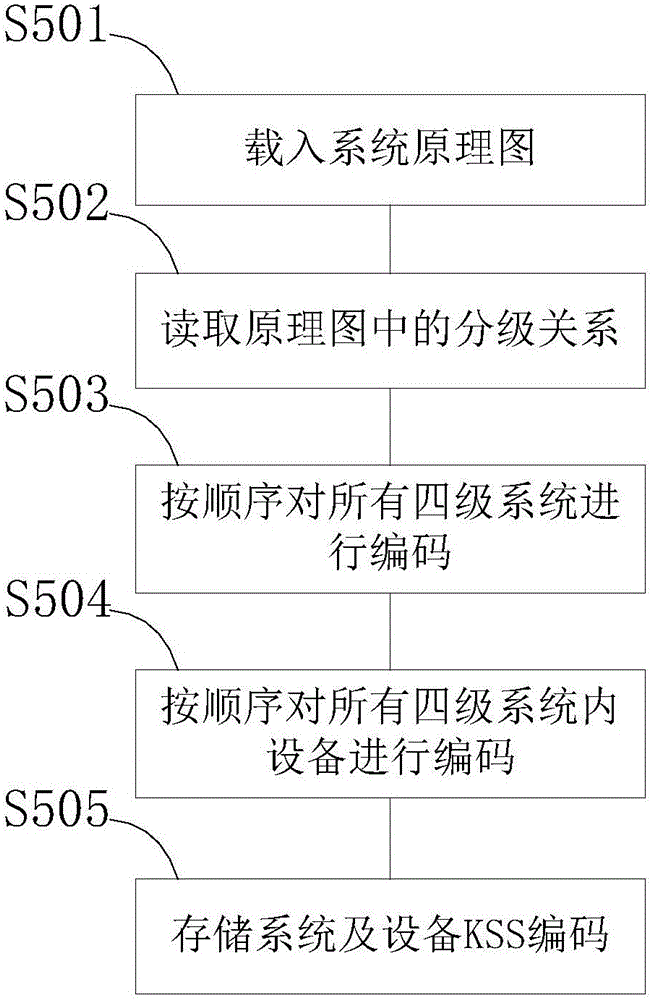
The invention discloses an intelligent encoding method for hydropower station equipment, mainly comprising the following steps of building a standard element library, building a KKS encoding database of equipment classes and levels, building a system level database, drawing a system principle diagram, selecting the equipment and determining the system level in the system level database according to the actual station design, connecting the elements to generate a system principle diagram, and generating an equipment KKS encoding database to complete the KKS encoding automatic arrangement and storage of the equipment in the system principle diagram. The standard element library, the equipment and the system encoding database are adopted, so the system principle diagram is easy to draw, the artificial interference is reduced for encoding, the equipment KKS encoding efficiency is improved, the uniformity, integrity, accuracy and continuity of the encoding are guaranteed, and for the system design change, the system encoding and annotation can be updated immediately, and the unified management of the station KKS is realized.

Description

technical field [0001] The invention relates to the technical field of power generation equipment management, in particular to a method for intelligently coding hydropower station equipment using the process identification principle in the KKS ("power plant identification system") encoding system. Background technique [0002] The planning, construction and management of hydropower stations is an extremely complex process. At present, the KKS coding system is widely used abroad for management. KKS is the abbreviation of Kraftwerk-Kennzeichen-System in German, that is, "power plant identification system". A code that uniquely identifies units, systems, equipment and components within a hydropower station. KKS has three different types of identifications: process identification, installation point identification and position identification. The emphases of the three types of identification applications are different. Among them, the process identification can be unified acco...

Claims


Application Information

Patent Timeline
IPC IPC(8): G06F17/30G06Q10/06G06Q50/06
CPCG06F16/21G06Q10/06G06Q50/06
Inventor 邹海青陈冬波刘景旺田子勤郑涛平胡定辉代开锋何志锋段威金德山柳飞何峰
Owner CHANGJIANG SURVEY PLANNING DESIGN & RES
Learn More