Double-frequency dual-polarization narrow-wave beam array antenna

An array antenna, dual-polarization technology, applied in the field of communication, to achieve the effect of saving cost, compact structure and reducing the number of antennas

Active Publication Date: 2016-08-10
GUANGDONG BROADRADIO COMM TECH
View PDF6 Cites 11 Cited by
  • Summary
  • Abstract
  • Description
  • Claims
  • Application Information

AI Technical Summary

Problems solved by technology

[0004] Traditional narrow-beam antennas can only solve single-band coverage, that is, they only work at 698-960MHz or 1710-2690MHz

Method used


Image

  • Double-frequency dual-polarization narrow-wave beam array antenna
  • Double-frequency dual-polarization narrow-wave beam array antenna
  • Double-frequency dual-polarization narrow-wave beam array antenna

Examples


Embodiment 1

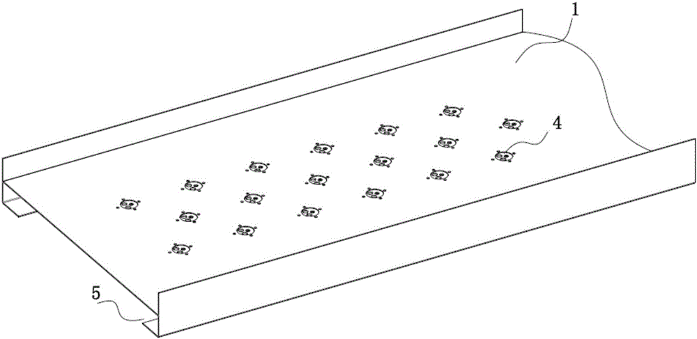
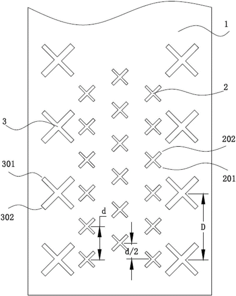
[0031] Such as Figure 2 to Figure 5 As shown, a dual-frequency dual-polarization narrow-beam array antenna provided by Embodiment 1 of the present invention includes a metal reflector 1, a high-frequency radiation unit 2 that is installed on the metal reflector and works in a higher frequency band and works in a lower Band low frequency radiating unit 3. Preferably, the high-frequency radiation unit 2 works in the frequency range of 1710-2690 MHz, and the low-frequency radiation unit 3 works in the frequency range of 698-960 MHz.

[0032] The metal reflector 1 is partially hollowed out, and a plastic base 4 is installed on which the high-frequency radiation unit 2 is installed, which avoids physical direct connection between the metal reflector 1 and the high-frequency radiation unit 2 . The metal reflector 1 is directly connected to the low frequency radiation unit 3 through metal screws. The electromagnetic coupling between the high and low frequency radiation units is re...

Embodiment 2

[0042] Such as Image 6 As shown, the embodiment of the present invention is changed on the basis of embodiment 1, and the high-frequency system can only provide high-quality radiation performance in the frequency band of 1710-2170 MHz. Considering the actual requirements of the network and cost factors, this kind of dual-frequency dual-polarization narrow-beam array antenna has great practical value.

[0043] Specifically, the high-frequency system in the embodiment of the present invention has only two columns of high-frequency arrays, and the high-frequency arrays are still arranged at equal intervals. The corresponding radiation units between the two columns are connected by two power dividers. The frequency range of the power divider is 1710-2170MHz.

[0044] Specifically, two rows of low-frequency arrays are respectively located on both sides of the high-frequency array, and the low-frequency arrays are also arranged at equal intervals. Preferably, the interval is twice...


PUM


Abstract

The invention relates to a double-frequency dual-polarization narrow-wave beam array antenna comprising a metal reflecting plate, high-frequency radiating units, and low-frequency radiating units. The high-frequency radiating units arranged on the metal reflecting plate work at a high frequency band and the low-frequency radiating units arranged on the metal reflecting plate work at a low frequency band. Two columns of low-frequency arrays are distributed at the two sides of three columns of high-frequency arrays; the low-frequency radiating units corresponding to the two columns of low-frequency arrays are connected by two paths of power divider and all low-frequency arrays form a low-frequency system; the high-frequency radiating units corresponding to the three columns of high-frequency arrays are connected by three paths of power dividers and all high-frequency arrays form a high-frequency system. Because of a high-low-frequency non-common-ground way and a corresponding de-coupling device, independence of the high-frequency and low-frequency circuits and radiating performances is guaranteed. With the double-frequency dual-polarization narrow-wave beam array antenna, stability of the radiating characteristic in a broadband range is guaranteed; and compatibility with all 2G, 3G and 4G LTE systems in mobile communication is realized.

Description

technical field [0001] The invention relates to the communication field, and more specifically relates to a dual-frequency dual-polarization narrow-beam array antenna. Background technique [0002] As an important means of information transmission, communication technology is constantly developing under the promotion of the deepening of modern society's informatization process. The base station antenna is a system component that radiates and receives electromagnetic waves, and plays an important role in "uploading and distributing" in the entire mobile communication system. The performance of the antenna directly affects the quality of mobile communication. A high-performance antenna can not only relax the requirements of the communication system but also improve the performance of the whole system. In order to be compatible with multiple communication systems and reduce system complexity and network construction costs, broadband, miniaturization, and multi-frequency sharin...

Claims


Application Information

Patent Timeline
Patent Type & Authority Applications(China)
IPC IPC(8): H01Q21/24H01Q5/20H01Q5/30
CPCH01Q5/20H01Q5/30H01Q21/24
Inventor 邱柯芳章秀银孙丹吴壁群张鹏苏振华
Owner GUANGDONG BROADRADIO COMM TECH
Why Eureka
Try Eureka