Color sorting machine

A technology of color sorter and conveying mechanism, applied in the field of color sorter, can solve the problems of improper adjustment, need to stop and adjust again, prone to shadows, inconvenient adjustment of material baffles, etc., to achieve good recognition effect and avoid errors , Adjust the effect of convenient and quick

Active Publication Date: 2016-08-17
LANXI BOYUAN
View PDF7 Cites 2 Cited by
  • Summary
  • Abstract
  • Description
  • Claims
  • Application Information

AI Technical Summary

Problems solved by technology

The optical signal acquisition mechanism is a crucial core component, which is directly related to the effect of sorting. The optical signal acquisition mechanism includes an illumination system and an image collector. For images, if the light cannot be evenly illuminated on the surface of the material, and it is only illuminated from one direction, shadows are likely to appear on the backlight side of the material, and the shadows are likely to cause color deviations in the collected images and cause sorting errors; on the other hand, With the long-term use of the equipment, due to the dust carried by the material, the lower end surface (light incident end surface) of the image collector will be covered with a layer of dust, which needs to be cleaned frequently, but because the image collector is installed in the casing , it is very inconvenient to open the case when cleaning; moreover, long-term use will cause the white balance of the image collector to deviate, resulting in inaccurate colors of the collected images, which will affect the sorting effect and cause large errors
The color sorter in the prior art still has the defect t

Method used


Image

  • Color sorting machine
  • Color sorting machine
  • Color sorting machine

Examples


Example Embodiment

[0024] Hereinafter, the present invention will be further described in detail through the drawings and specific embodiments.

[0025] Such as figure 1 , 2 As shown in 3, this embodiment provides a color sorter, which includes a conveying mechanism 1 and an optical signal collection mechanism and a sorting actuator located inside the housing 100.

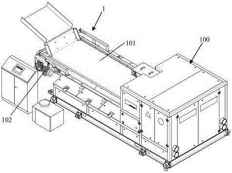
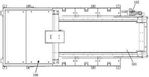
[0026] The conveying mechanism 1 is arranged on the front side of the optical signal collecting mechanism, and is used to convey materials to the optical signal collecting mechanism and throw it up; the conveying mechanism 1 includes a horizontally arranged conveyor belt 101 and drives the conveyor belt 101 to rotate The pulley and the motor 102 that drives the pulley to rotate.
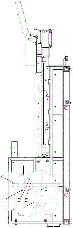
[0027] The optical signal collection mechanism includes an illumination system 21 and an image collector 22, the illumination system 21 is located above the trajectory where the material is thrown, and the image collector 22 is located above the illumination syste...


PUM


Abstract

The invention discloses a color sorting machine comprising a conveying mechanism, an optical signal acquisition mechanism and a sorting actuator; the conveying mechanism is arranged on the front side of the optical signal acquisition mechanism and used for conveying a material to an optical signal acquisition mechanism and tossing; the optical signal acquisition mechanism includes an illumination system and an image acquisition device; the illumination system is located above a material tossing track, and the image acquisition device is located above the illumination system; the illumination system comprises two striped lamp tubes horizontally arranged and perpendicular to the conveying direction of a conveying belt, the tubes are each arranged in a lampshade, and the two lampshades are arranged at intervals; the image acquisition device is arranged just above a gap between the two lampshades; light illuminated from the two lampshade illuminates downwards tilted and are intersected just below the gap. By adopting the color sorting machine, a local shadow can be prevented from being generated on the upper end face of the material, so that the image acquisition device can acquire a clear material image, the error is avoided, and good recognition effect is achieved.

Description

technical field [0001] The invention relates to a color sorter, in particular to the technical field of copper waste recycling and sorting. Background technique [0002] The color sorter is a device that uses photoelectric detection technology to automatically sort out the different-color particles in the granular material according to the difference in the optical characteristics of the material. As an excellent material sorting equipment, the color sorter is widely used in grain processing, ore sorting and other industries. The color sorter as a whole includes key components such as the conveying mechanism, optical signal acquisition mechanism, and sorting actuator. The material is transported to the optical signal acquisition mechanism through the conveying mechanism, and the image data of the material is collected by the optical signal acquisition mechanism and analyzed by the host computer. After the analysis, the sorting actuator is used to separate the materials to be...

Claims


Application Information

Patent Timeline
IPC IPC(8): B07C5/342B07C5/02B07C5/36B08B1/00
Inventor 徐浩军
Owner LANXI BOYUAN
Why Eureka
Try Eureka