
Vertical metal machining machine

A metal processing and vertical technology, applied in metal processing, metal processing mechanical parts, metal processing equipment, etc., can solve the problems of reducing the service life of the spindle and even the driving mechanism, reducing the production quality and efficiency, and reducing the service life of the machine tool, etc. The effect of increased rigidity, improved efficiency, and reduced tool change time

Inactive Publication Date: 2016-08-17
DONGGUAN JIR FINE MACHINERY
View PDF16 Cites 13 Cited by
  • Summary
  • Abstract
  • Description
  • Claims
  • Application Information

AI Technical Summary

Problems solved by technology

[0003] The body of the metal processing machine in the prior art is relatively light and thin, and it is easy to deform during the high-speed machining process, resulting in a reduction in machining accuracy, lowering the quality and efficiency of production, and the main shaft connection method used by the general machine tool main shaft is simple , the moving method of the workpiece is also the traditional sliding form, which is easy to cause the deformation of the spindle or reduce the service life of the spindle or even the driving mechanism due to overheating during the processing process. Sliding increases the wear of the guide rail and further reduces the use of the machine tool lifetime and increased production costs

Method used


Image

  • Vertical metal machining machine
  • Vertical metal machining machine
  • Vertical metal machining machine

Examples


Embodiment Construction

[0025] In order to facilitate the understanding of those skilled in the art, the present invention will be further described below in conjunction with the embodiments and accompanying drawings, and the contents mentioned in the embodiments are not intended to limit the present invention.

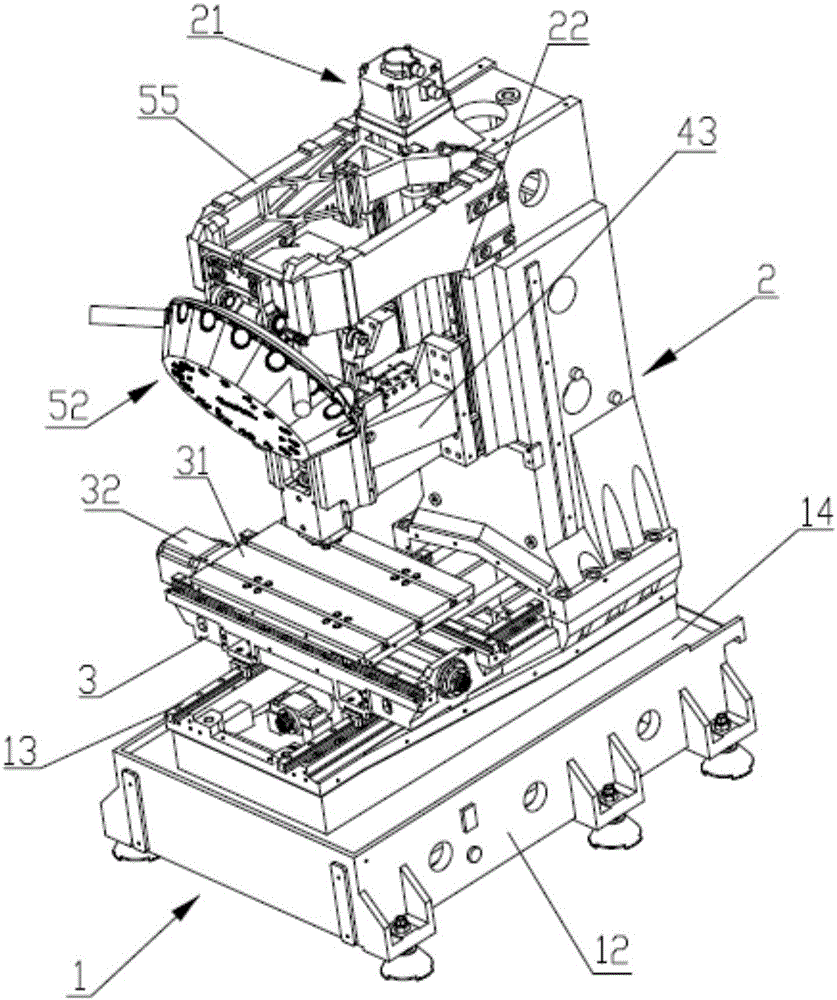
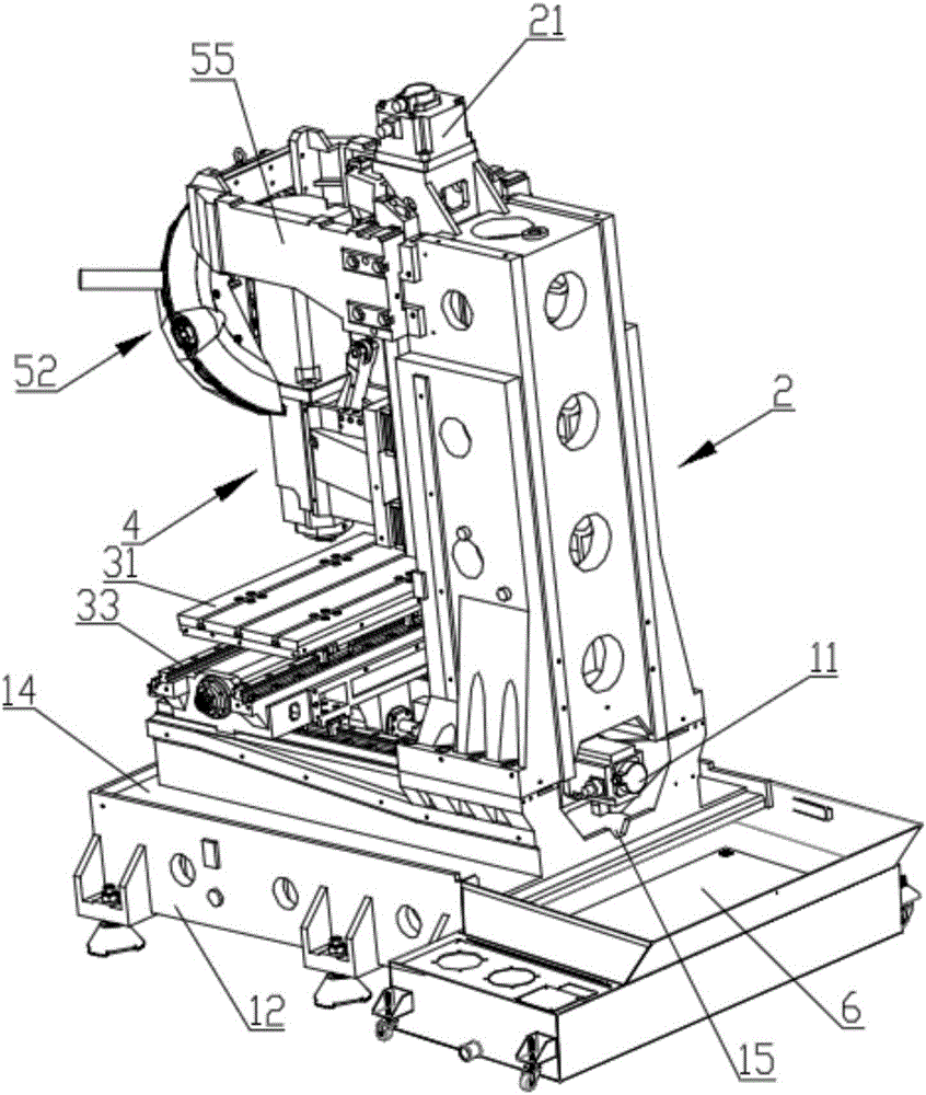
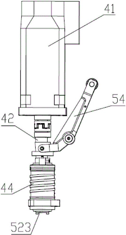
[0026] Such as Figure 1~4 As shown, a vertical metal processing machine includes a base 1, a column 2 arranged at one end of the base 1, a saddle 3 slidably arranged in the Y-axis direction of the base 1, and a saddle 3 slidably arranged in the X-axis direction of the saddle 3 and used The workbench 31 where the workpiece is placed, the processing device 4 that is slid on the Z-axis direction of the column 2 and is located above the worktable 31 for processing the workpiece, is installed on the side of the processing device 4 away from the column 2 for tool change synchronization The tool changer, the Y-axis drive device 11 that drives the saddle 3 to move along the base 1, the X-axis drive...


PUM


Abstract

The present invention relates to the field of metal processing equipment, in particular to a vertical metal processing machine, which includes a base, a column, a saddle, a workbench, a processing device, and a lifting drive device installed in the direction of the X-axis sliding on the saddle. Synchronous tool changing device, Y-axis driving device, X-axis driving device, Z-axis driving device, and collecting device for tool changing on one side; the synchronous tool changing device includes a head, a tool changing power mechanism and a rotatable tool magazine. The knife power mechanism drives and connects the knife magazine. The bottom of the head is equipped with a knife loading part, and a knife release mechanism is set beside the knife loading part. The knife magazine is equipped with multiple tool pockets for installing knives. The knife-loading opening is located directly below the knife-loading part. The base structure of the invention is stable, can bear the inertia generated by high-speed motion, has high machining accuracy and efficiency, and effectively improves the load that can be borne by machining.

Description

technical field [0001] The invention relates to the field of metal processing equipment, in particular to a vertical metal processing machine. Background technique [0002] Metal processing machines are metal processing machine tools, also called CNC machine tools, referred to as machining centers (the English name is Computerized Numerica1 Contro1 Machine referred to as cnc). Metal processing center is a high-efficiency automatic machine tool suitable for processing complex-shaped workpieces, which is usually composed of control system, servo system, detection system, mechanical transmission system and other auxiliary systems. [0003] The body of the metal processing machine in the prior art is relatively light and thin, and it is easy to deform during the high-speed machining process, resulting in a reduction in machining accuracy, lowering the quality and efficiency of production, and the main shaft connection method used by the general machine tool main shaft is simple ...

Claims


Application Information

Patent Timeline
Patent Type & Authority Applications(China)
IPC IPC(8): B23Q37/00B23Q3/155B23Q11/00
CPCB23Q37/00B23Q3/155B23Q11/0042
Inventor 蒋修华
Owner DONGGUAN JIR FINE MACHINERY
Learn More