Adjustment method for outer shape of ground component
An adjustment method and technology of components, applied in the directions of grinding devices, grinding machine tools, metal processing equipment, etc., can solve the problems of uneven surface of grinding wafers, scratched wafers by grinding wafers, and short service life of grinding components, and achieve the grinding removal rate. Consistent, save grinding cost, improve the effect of grinding uniformity
- Summary
- Abstract
- Description
- Claims
- Application Information
AI Technical Summary
Problems solved by technology
Method used
Image
Examples
Embodiment 1
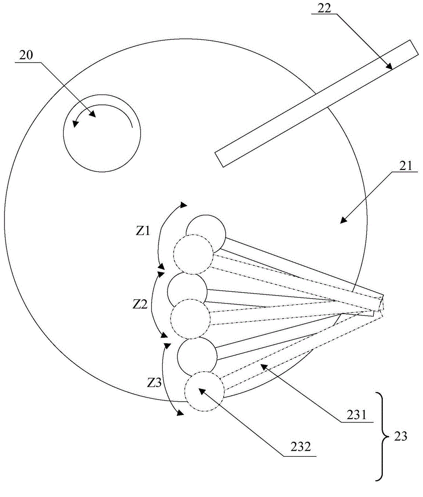
[0058] see image 3 , the invention provides a method for adjusting the shape of a grinding part, the method for adjusting the shape of a grinding part at least includes the following steps:
[0059] 1) Provide a grinding component 21 and a grinding adjustment device 23 for adjusting the shape of the grinding component 21, the grinding adjustment device 23 includes an adjustment disc 232 and a transmission shaft 231 that drives the adjustment disc 232 to swing;
[0060] 2) Place the adjusting disc 232 on the grinding member 21 and swing it. The swing track of the adjusting disc 232 is composed of a plurality of swinging areas; the adjusting disc 232 is in each of the swinging areas. At least one of the swing duration, the swing speed and the applied pressure is different from each other.
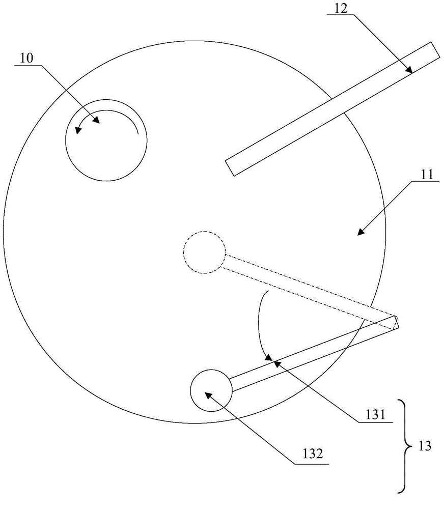
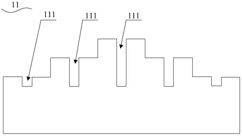
[0061] Specifically, the adjustment process can be carried out synchronously with the grinding process, that is, as figure 2 As shown, the grinding head 20 of the wafer to be ground is pl...
Embodiment 2
[0076] read on image 3 , the present invention also provides a method for adjusting the shape of the grinding component. The adjustment method in this embodiment is substantially the same as the adjustment method in Embodiment 1. difference. In this embodiment, the method for adjusting the swing of the disk 232 includes at least the following steps:
[0077] 21) The adjusting disc 232 is under the first pressure and swings in the first swinging zone Z1 at a first swinging speed, and the duration of the adjusting disc 232 swinging in the first swinging zone Z1 is the second a long time;
[0078] 22) Adjust the pressure and swing speed of the adjustment disk 232, so that the adjustment disk 232 swings in the second swing zone Z2 at a second swing speed under the second pressure, and the adjustment circle The time period during which the disc 232 oscillates in the second oscillating zone Z2 is the second time period;
[0079] 23) Adjust the pressure and swing speed of the adju...
Embodiment 3
[0085] Please combine image 3 refer to Figure 5 , the present invention also provides a method for adjusting the shape of the grinding component. The adjustment method in this embodiment is substantially the same as the adjustment method in Embodiment 1. The difference between the two is only in the method for adjusting the specific oscillation of the disc 232. Between steps 23) and 24), it also includes adjusting the pressure and the swing speed of the adjustment disc 232, so that the adjustment disc 232 swings at the fourth swing speed at the fourth pressure under the fourth pressure. The step of oscillating zone Z4, the fourth oscillating zone Z4 is the entire oscillating track of the adjustment disc 232, that is, the fourth oscillating zone Z4 is the first oscillating zone Z1, the second oscillating zone The sum of Z2 and the third swing zone Z3, that is, the starting point of the fourth swing zone Z4 is at a distance of about 1.65 inches from the edge of the grinding m...
PUM
 Abstract
Description
Claims
Application Information
 - R&D
- Intellectual Property
- Life Sciences
- Materials
- Tech Scout
- Unparalleled Data Quality
- Higher Quality Content
- 60% Fewer Hallucinations
Browse by: Latest US Patents, China's latest patents, Technical Efficacy Thesaurus, Application Domain, Technology Topic, Popular Technical Reports.
© 2025 PatSnap. All rights reserved.Legal|Privacy policy|Modern Slavery Act Transparency Statement|Sitemap|About US| Contact US: help@patsnap.com


