Brake energy recovery and release device

A technology of braking energy recovery and release device, applied in the directions of brakes, braking components, transportation and packaging, can solve the problems of extra work, loss, complex structure, etc., and achieve the effects of simple control, low cost and simple structure

Active Publication Date: 2018-08-28
张晓春
View PDF7 Cites 0 Cited by
  • Summary
  • Abstract
  • Description
  • Claims
  • Application Information

AI Technical Summary

Problems solved by technology

However, there are shortcomings in various aspects such as complex structure, loss, and need for additional work, which are well known in the industry.

Method used


Image

  • Brake energy recovery and release device
  • Brake energy recovery and release device
  • Brake energy recovery and release device

Examples


Embodiment Construction

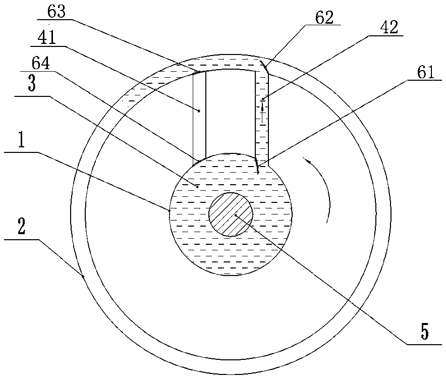
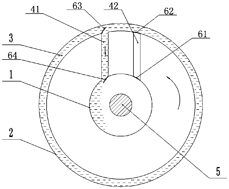
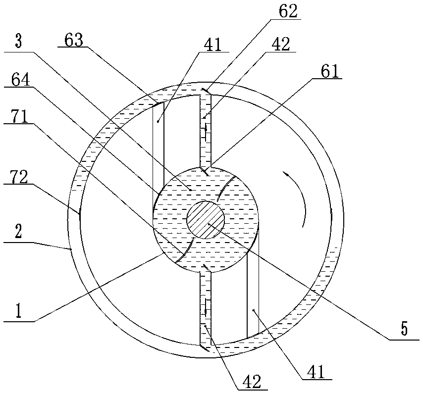
[0024] Figure 1-Figure 2 The brake energy recovery and release device shown includes an inner ring 1 and an outer ring 2 both having cavities, and the diameter of the inner ring 1 is smaller than that of the outer ring 2, and there is a liquid fluid 3 in the cavity of the inner ring 1 and the outer ring 2 There is a guide channel through which the liquid fluid 3 passes between the inner ring 1 and the outer ring 2, and the guide channel includes a return channel 41 and an outflow channel 42, and the liquid fluid flows inward from the outer ring 2 in the return channel 41 The ring 1 flows, and the liquid fluid flows from the inner ring 1 to the outer ring 2 in the outflow channel 42, and at least one of the inner ring 1, the outer ring 2 and the guide channel is connected with the rotating shaft 5 ( Figure 6 ), a valve is provided at the connection between the guide channel and the inner ring 1 and the outer ring 2.

[0025] The interior of the inner ring 1, the outer ring 2...


PUM


Abstract

The invention relates to a brake energy recovery and release device. The brake energy recovery and release device comprises an inner ring and an outer ring, wherein the inner ring and the outer ring are respectively provided with a cavity, the diameter of the inner ring is greater than the diameter of the outer ring, and a liquid fluid is filled into the cavities of the inner ring and the outer ring; a flow guide passage is arranged between the inner ring and the outer ring, and the liquid fluid can pass through the flow guide passage; at least one of the inner ring, the outer ring and the flow guide passage is connected with a rotary shaft, and valves are arranged at the connecting parts of the flow guide passage and the inner ring and outer ring. The brake energy recovery and release device has the advantages that by utilizing the flowing of liquid fluid in the two hollow rings, the effects of brake deceleration and starting acceleration are realized; the brake energy recovery and release device is suitable for the equipment or working state with frequent brake and starting, and can assist to improve the brake and starting force. The invention also discloses an automobile brake energy recovery and release device, which comprises the brake energy recovery and release device; the brake energy recovery and release device is connected with wheels, so that the effects of energy saving and consumption decrease are realized.

Description

technical field [0001] The invention belongs to the technical field of braking energy recovery and release. Background technique [0002] For equipment that brakes and starts frequently, such as a car traveling in a city, when braking, the kinetic energy of the car body is converted into heat from the brake pads, which is wasted in vain. Starting and accelerating is a process that consumes energy, especially in traffic jams. Energy waste is even more serious, and in vehicles, the energy consumption of starting acceleration consumes more energy than moving at a constant speed for the same distance. There are many similar scenarios, such as elevators, industrial automation assembly, etc., which will brake and start frequently, which can only waste a lot of energy in vain. There are still many equipments that frequently accelerate and decelerate, such as punch presses, compression / work processes of 2-stroke diesel engines, etc., which have uneven force, so the mass of inertial...

Claims


Application Information

Patent Timeline
Patent Type & Authority Patents(China)
IPC IPC(8): B60T1/10
CPCB60T1/10
Inventor 张晓春杭星光张忠
Owner 张晓春
Why Eureka
Try Eureka