Airplane cockpit control system and method

A control system and cockpit technology, which is applied in the aircraft cockpit control system and the field of control, can solve the problems of increased wiring, difficult integration, and a large number of cables, and achieves a reduction in the number of cables, strong real-time acquisition, and anti-corrosion Disruptive effect

Active Publication Date: 2016-08-17
BEIJING AERONAUTIC SCI & TECH RES INST OF COMAC +1
View PDF2 Cites 17 Cited by
  • Summary
  • Abstract
  • Description
  • Claims
  • Application Information

AI Technical Summary

Problems solved by technology

[0004] figure 1 It is a schematic diagram of the structure of the traditional cockpit control system. The problem brought about by this implementation method is that the system integration is complicated: 1. The sensor of the driver's control part is powered by the flight control electronics, and the flight control electronics provides signal calculation, and the system has strong cross-linking. , strong coupling, difficult integration
2. The RVDT sensor is complicated, each sensor is composed of 5 wires, and in order to ensure the redundancy, each operating mechanism is equipped with multiple RVDT sensors, which brings the complexity of implementation, increases the number of wiring, and increases the weight
[0010] 1. The integration complexity is high; in order to realize the acquisition of cockpit control signals, it is necessary to deploy multiple sensors between the control components, and at the same time, it is necessary to collect and solve analog signals in the flight control electronics, and the system has a large degree of cross-linking. Strong coupling, high complexity in interface definition and implementation, and difficult integration;
[0011] 2. The number of cables is large, and the volume and weight are large; each operating mechanism is equipped with multiple RVDT sensors in order to ensure redundancy, and each sensor needs 5 wires to complete the function, resulting in a large number of cables and a large volume of the system. with heavy weight;
[0012] 3. Low system reconfigurability

Method used


Image

  • Airplane cockpit control system and method
  • Airplane cockpit control system and method
  • Airplane cockpit control system and method

Examples


Embodiment Construction

[0034] Specific embodiments of the present invention will be described in detail below in conjunction with specific drawings. It should be noted that the technical features or combinations of technical features described in the following embodiments should not be regarded as isolated, and they can be combined with each other to achieve better technical effects. In the drawings of the following embodiments, the same reference numerals appearing in each drawing represent the same features or components, which can be applied in different embodiments.

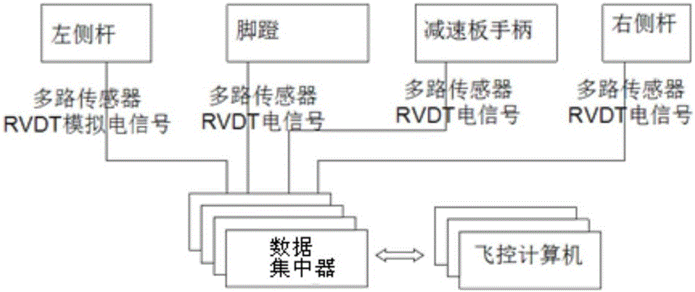
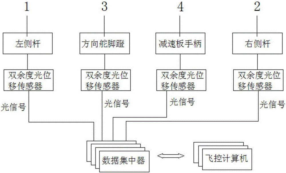
[0035] Such as image 3 As shown, a kind of aircraft cockpit control system of the embodiment of the present invention comprises side stick 1,2 (being respectively left side stick 1, right side stick 2, also can have other side stick arrangements), rudder pedal 3, The speed brake handle 4, the throttle platform, the side sticks 1, 2, the rudder pedals 3, and the speed brake handle 4 are all connected to the data concentrator throu...


PUM


Abstract

The invention relates to the technical field of flying control, and provides an airplane cockpit control system. The system comprises side rods, rudder pedals and an air brake handle. Each side rod is connected with four dual-redundancy optical displacement sensors, each dual-redundancy optical displacement sensor is connected with two ACEs (data concentrators), and each side rod is connected with four ACEs through eight optical cables. Each rudder pedal is connected with one dual-redundancy optical displacement sensor, each dual-redundancy optical displacement sensor is connected with two ACEs, and each rudder pedal is connected with two ACEs through two optical cables. The air brake handle is connected with two dual-redundancy optical displacement sensors, each dual-redundancy optical displacement sensor is connected with two ACEs, and the air brake handle is connected with four ACEs through four optical cables. The airplane cockpit control system has the advantages that system deployment is simple, efficient and modular, and integration is easy; redundancy configuration is reasonable, and the number of the cables is small; the optical displacement sensors are used, so that signal collecting real-time performance is better, and anti-interference performance is higher.

Description

technical field [0001] The invention relates to the technical field of aircraft flight control, in particular to an aircraft cockpit control system and a control method. Background technique [0002] The flight control system of an aircraft is generally composed of a cockpit control system, flight control electronics and actuators. The cockpit control system mainly realizes the driver's control command input, and the flight control electronics mainly realizes the solution of the control law according to the pilot's command. , and output to the actuator for execution; the actuator system deflects the rudder surface of the aircraft according to the instructions of the flight control electronics, and realizes the closed-loop control of the rudder surface. [0003] The traditional cockpit control system is composed of side sticks, pedals, and speed brake handles. The input of the driver's control is realized by the RVDT sensor installed with each control mechanism. The flight co...

Claims


Application Information

Patent Timeline
Patent Type & Authority Applications(China)
IPC IPC(8): B64C13/16
CPCB64C13/16
Inventor 白志强熊斯雷宇陈少敏
Owner BEIJING AERONAUTIC SCI & TECH RES INST OF COMAC
Why Eureka
Try Eureka