T-shaped through clapboard-type multi-chamber concrete filled steel tube combination column and steel beam joint and assembly method thereof

A technology of steel pipe concrete and multi-chamber, which is applied in the direction of construction and building construction, can solve the problems of high manufacturing cost and complex structure of multi-chamber steel pipe concrete composite column-beam-column joints, and reduce environmental pollution and welding The effect of workload and material saving

Active Publication Date: 2016-08-17
XI'AN UNIVERSITY OF ARCHITECTURE AND TECHNOLOGY
View PDF8 Cites 4 Cited by
  • Summary
  • Abstract
  • Description
  • Claims
  • Application Information

AI Technical Summary

Problems solved by technology

[0005] In order to solve the problems of complex structure and high manufacturing cost of existing multi-chamber concrete-filled steel pipe composite column-beam-column joints, the purpose of the present invention is to provide a T-shaped penetrating partition type multi-chamber concrete-filled steel pipe composite column I-beam joint And assembly method, simple structure, convenient and quick construction, convenient for industrial production, high material utilization rate, which is conducive to saving materials and reducing costs

Method used


Image

  • T-shaped through clapboard-type multi-chamber concrete filled steel tube combination column and steel beam joint and assembly method thereof
  • T-shaped through clapboard-type multi-chamber concrete filled steel tube combination column and steel beam joint and assembly method thereof
  • T-shaped through clapboard-type multi-chamber concrete filled steel tube combination column and steel beam joint and assembly method thereof

Examples


Embodiment Construction

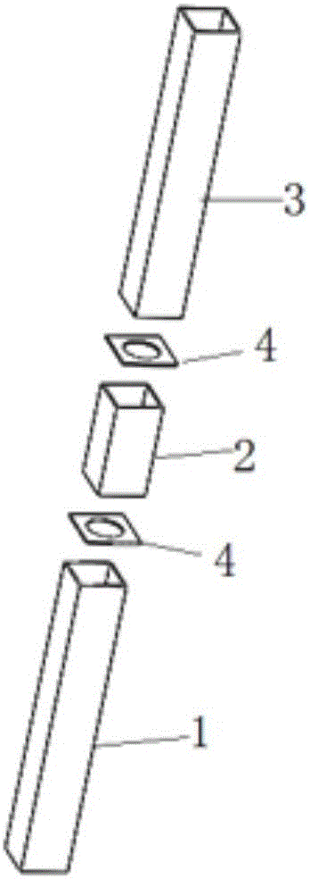
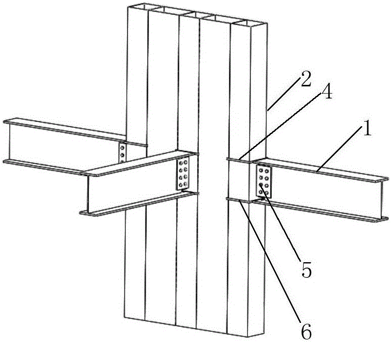
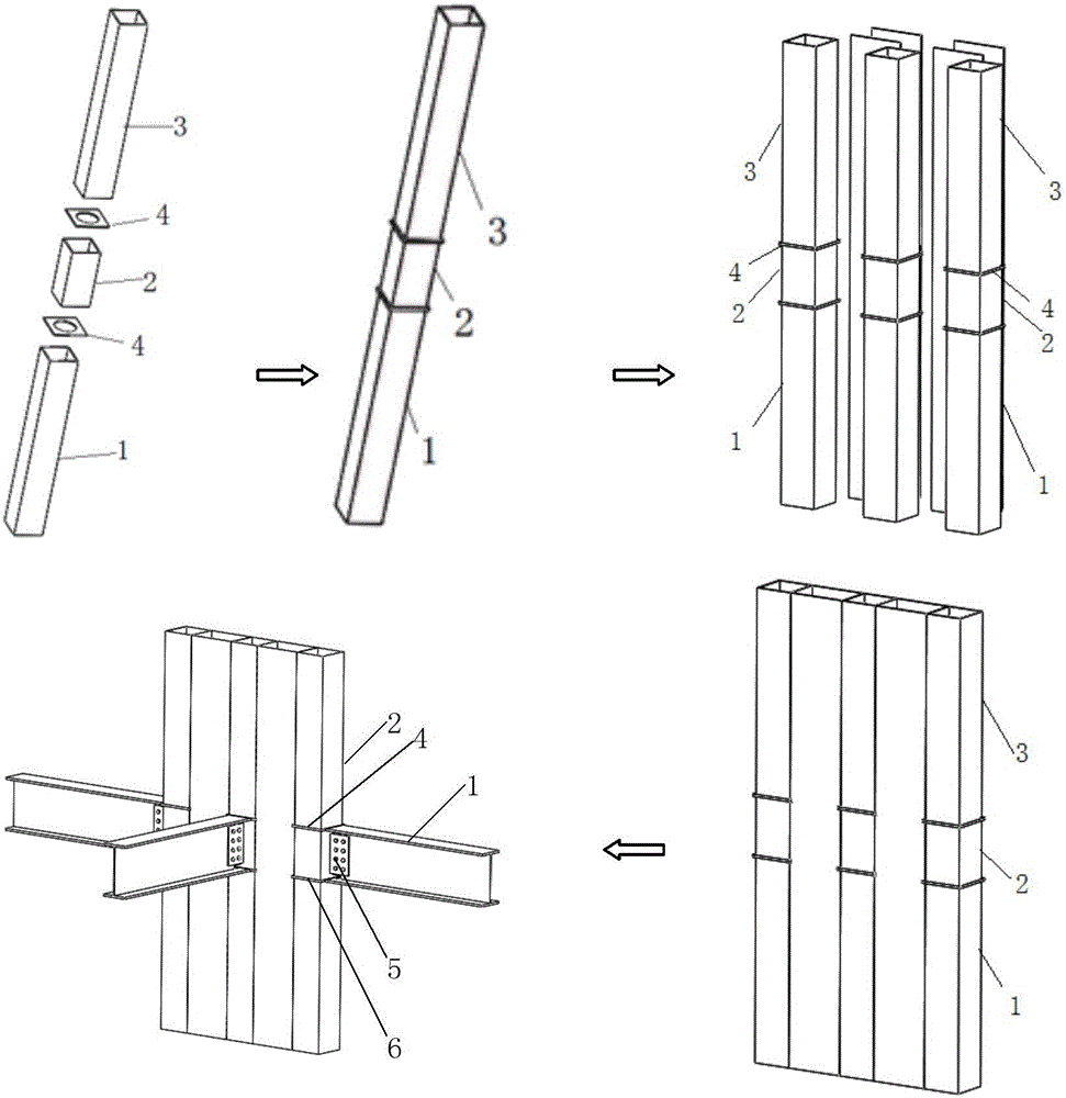
[0041] refer to Figure 1 to Figure 5 , the present invention comprises multi-chamber concrete-filled steel pipe composite columns, three concealed columns arranged at intervals in the multi-chamber steel-filled concrete composite columns, parallel webs are arranged between adjacent two concealed columns, and each concealed column is provided with The first through partition 4 and the second through partition 6 are provided with through holes. Both the first penetrating partition 4 and the second penetrating partition 6 are set horizontally and protrude from hidden columns. The first penetrating partition 4 is connected to the upper flange of the I-shaped steel beam 1, and the second penetrating partition 6 is connected to the I-shaped beam. The lower flange of steel beam 1 is connected. The web of the I-beam 1 is connected to the multi-chamber concrete filled steel pipe composite column 2 through a connecting plate 5 . The dark pillars comprise the first section of dark pil...


PUM

PropertyMeasurementUnit
lengthaaaaaaaaaa

Abstract

The invention relates to a T-shaped through clapboard-type multi-chamber concrete filled steel tube combination column and steel beam joint and an assembly method thereof. The T-shaped through clapboard-type multi-chamber concrete filled steel tube combination column and steel beam joint comprises a multi-chamber concrete filled steel tube combination column and an I-steel beam, wherein the multi-chamber concrete filled steel tube combination column comprises three embedded columns which are arranged at intervals, and parallel web plates are arranged between two adjacent embedded columns; a first through clapboard and a second through clapboard are arranged on each embedded column and are horizontally arranged and extend out of the embedded column, and the first through clapboard is connected with the top flange of the I-steel beam; the second through clapboard is connected with the bottom flange of the I-steel beam. The through clapboards fully penetrate through the embedded columns, the lateral dimension of the clapboard is wider than the beam, and the beam web plates are connected with the multi-chamber concrete filled steel tube combination column through double connecting plates to achieve a design guideline of strong column and weak beam, strong joint and weak rod piece. Because the through clapboards only penetrate through the embedded columns, a column cross-section is less weakened, and the vertical transmitting force of the multi-chamber concrete filled steel tube combination column is effectively ensured.

Description

technical field [0001] The invention relates to an I-shaped steel beam node of a T-shaped penetrating partition type multi-chamber concrete filled steel pipe composite column and an assembly method. Background technique [0002] Steel structure is an industrialized building system that meets the requirements of building industrialization standards for standardized design, factory production, assembly construction, and information management. On-site assembly construction saves a lot of labor, and has less construction waste, energy saving and environmental protection. In the steel structure system, steel columns, steel beams, supports and other components still have a considerable proportion of artificial production. Most of the steel columns are square and rectangular columns. In residential applications, there are steel column convex corners indoors, which brings inconvenience to architectural layout. . [0003] The traditional concrete structure requires a lot of labor ...

Claims


Application Information

Patent Timeline
Patent Type & Authority Applications(China)
IPC IPC(8): E04B1/58E04B1/30
CPCE04B1/30
Inventor 郝际平黄育琪薛强孙晓岭樊春雷刘斌陈永昌王磊刘瀚超何梦楠尹伟康赵子健张峻铭
Owner XI'AN UNIVERSITY OF ARCHITECTURE AND TECHNOLOGY
Why Eureka
Try Eureka