Middle valve structure used for continuous variable valve timing system

A technology of valve timing and center valve, applied in the direction of non-mechanical actuated valves, valve devices, engine components, etc., can solve the problems of long length and complex structure, and achieve simple structure, low cost, and meet the changing needs Effect

Active Publication Date: 2016-08-17
JAPHL POWERTRAIN SYST
View PDF8 Cites 6 Cited by
  • Summary
  • Abstract
  • Description
  • Claims
  • Application Information

AI Technical Summary

Problems solved by technology

In the center valve structure in the prior art, there are three oil discharge holes P, A, and B on the surface of the valve sleeve (bolt) of the center valve structure, and the structure is relatively complicated and the length is relatively long

Method used


Image

  • Middle valve structure used for continuous variable valve timing system
  • Middle valve structure used for continuous variable valve timing system
  • Middle valve structure used for continuous variable valve timing system

Examples


Embodiment Construction

[0023] Below with reference to the accompanying drawings, through the description of the embodiments, the specific embodiments of the present invention, such as the shape, structure, mutual position and connection relationship between the various parts, the role and working principle of the various parts, etc., will be further described. Detailed instructions:

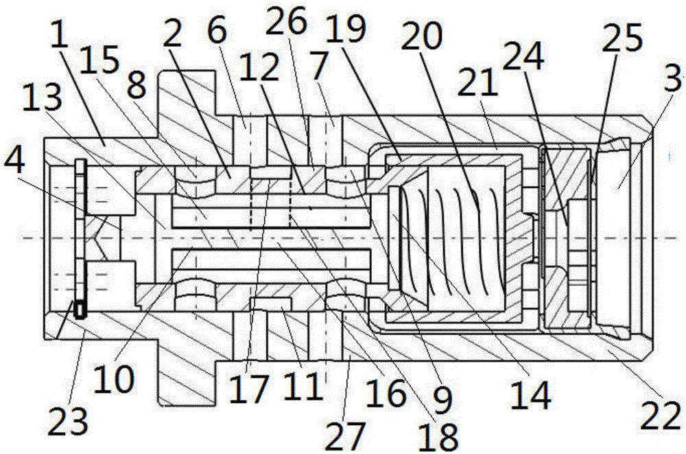
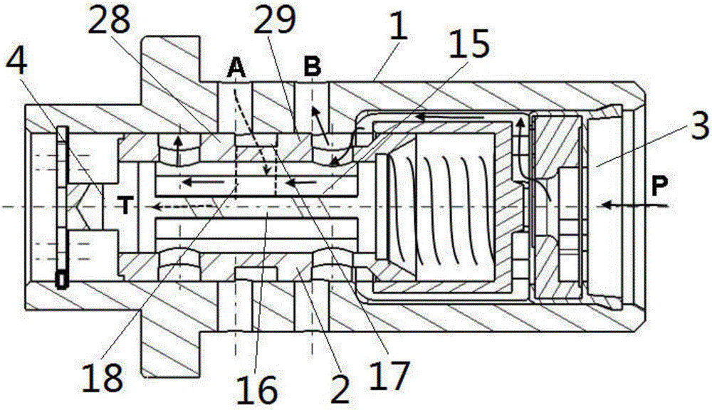
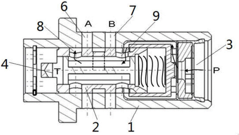
[0024] as attached figure 1 — attached Image 6 As shown, the present invention is a central valve structure for a continuously variable valve timing system. The central valve structure includes a valve sleeve 1 and a valve body 2, and an oil inlet is provided at one end of the valve sleeve 1 3. The other end of the valve sleeve 1 is provided with an oil return port 4, the oil inlet 3 is connected to the high-pressure oil passage of the engine, and the oil return port 4 is connected to the fuel tank. The valve sleeve 1 is provided with a valve sleeve oil hole A6 and a valve sleeve oil hole B7, the valve body 2 is set...


PUM


Abstract

The invention belongs to the technical field of continuous variable valve timing systems and provides a middle valve structure used for a continuous variable valve timing system. An oil inlet (3) is formed in one end of a valve sleeve (1) of the middle valve structure. An oil return port (4) is formed in the other end of the valve sleeve (1). The oil inlet (3) communicates with a high-pressure oil passage of an engine. The oil return port (4) communicates with an oil tank. A valve sleeve oil port A (6) and a valve sleeve oil port B (7) are formed in the valve sleeve (1). A valve body (2) is sleeved with the valve sleeve (1). A valve body oil port A (8) and a valve body oil port B (9) are formed in the valve body (2). A valve element (10) is arranged in the valve body (2). The valve body (2) is of a structure that the valve body (2) can move forwards and backwards in the valve sleeve (1) along a valve sleeve cavity (11). The middle valve structure is simple, the oil passage in the middle valve can be changed conveniently and rapidly, different oil passage directions are achieved, and the requirements of the variable valve timing system for changing the oil passage in the middle valve of the middle valve are met.

Description

technical field [0001] The invention belongs to the technical field of continuously variable valve timing systems, and more specifically relates to a central valve structure used in continuously variable valve timing systems. Background technique [0002] The continuously variable valve timing system (VVT system) can provide the best valve timing under most operating conditions of the engine, and it better solves the problem of dynamic performance under high speed and low speed, heavy load and small load. Economical contradictions, while improving exhaust emissions to a certain extent. Therefore, VVT technology is widely used in new automobile engines. Compared with the non-central VVT system solution, the central VVT system solution can shorten the oil passage of the engine oil in the whole system, reduce the leakage of engine oil, effectively improve the response speed and control accuracy of the phase mechanism, and reduce the oil consumption . In the center valve stru...

Claims


Application Information

Patent Timeline
Patent Type & Authority Applications(China)
IPC IPC(8): F01L1/344F01L9/02F01L9/10
CPCF01L1/344F01L9/10
Inventor 甄子源范礼丁万龙李雪涛邵璠张国立王换斌许亮
Owner JAPHL POWERTRAIN SYST
Why Eureka
Try Eureka