Chain transmission system

A technology of chain drive and sprocket, applied in the field of chain drive system, can solve the problems of high requirements on materials and heat treatment, high requirements on strength and wear resistance, and high manufacturing and use costs, so as to improve the transmission efficiency, improve the bearing capacity and structure. form a flexible effect

Inactive Publication Date: 2016-08-17
张应新
View PDF6 Cites 5 Cited by
  • Summary
  • Abstract
  • Description
  • Claims
  • Application Information

AI Technical Summary

Problems solved by technology

However, this kind of transmission structure has a large number of chain parts, and the operation noise is large.
What is more prominent is that the sprocket requires special equipment and special tools for processing, and the sprocket part of the sprocket has high requirements for strength and wear resistance, and the corresponding manufacturing materials and heat treatment requirements are high, and the sprocket is difficult to repair after damage, resulting in manufacturing and high cost

Method used


Image

  • Chain transmission system
  • Chain transmission system
  • Chain transmission system

Examples


Embodiment 1

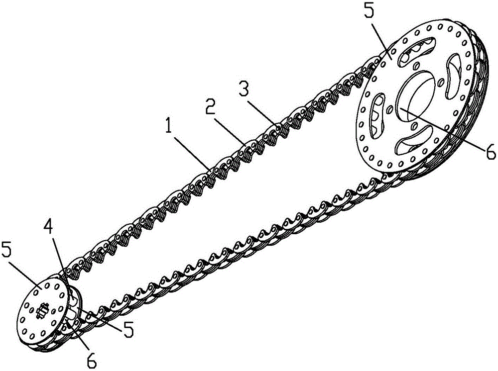
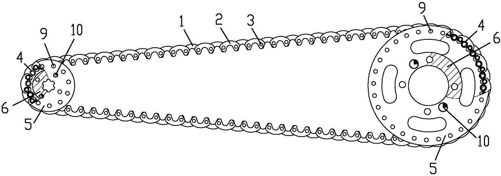
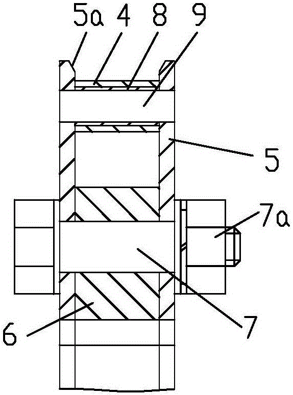
[0023] Example 1, see figure 1 , figure 2 , image 3 , Figure 4 , a chain drive system consisting of a figure 1 and figure 2 middle left drive sprocket, located in the figure 1 and figure 2 The driven sprocket on the right side of the middle, and the chain of the ring-shaped closed structure connected to the driving sprocket and the driven sprocket, the inner hole of the driving sprocket is a spline hole structure, and the driving sprocket and the driven sprocket include two The end disks 5 and the two end disks 5 are connected by the intermediate connecting cylinder 6 in the middle. Between the two end disks 5 on the outer periphery of the intermediate connecting cylinder 6, there are a plurality of rollers 4 forming sprockets evenly distributed on the circumference. The rollers 4 can be The rotating lining is lined with a sleeve 8, the sleeve 8 is set on the roller 9, and the two ends of the roller 9 are respectively fixed on the two end disks 5; the chain is compo...

Embodiment 2

[0028] Example 2, see Figure 5 , the head of the pin shaft 3 has a guide tapered surface 3b.

[0029] The rest of the structure of this embodiment is the same as that of Embodiment 1, and will not be repeated here.


PUM


Abstract

The invention discloses a chain transmission system, which comprises a driving sprocket, a driven sprocket and a chain with an annular closed structure. Constitutes an internally meshing toothed chain, the first chain link and the second chain link are staggered and hinged to each other through the pin shaft; the driving sprocket and the driven sprocket both include two end disks, and the two end disks are connected through the middle of the middle There are a plurality of rollers constituting chain teeth evenly distributed on the circumference between the two end disks connecting the outer circumference of the cylinder in the middle, and the two end disks also form side slip restrictions on the internal meshing toothed chain. The invention has the beneficial effects of small frictional resistance, low noise, high transmission efficiency, simple structure, low manufacturing difficulty, and low manufacturing and use costs.

Description

technical field [0001] The invention relates to a transmission system, in particular to a chain transmission system. Background technique [0002] The existing sleeve roller chain includes a driving sprocket, a driven sprocket and a chain. The chain is composed of an inner chain plate, an outer chain plate, a sleeve, a pin shaft and rollers. The outer chain plate is fixed on the pin shaft, and the inner chain plate is fixed on the pin shaft. The plate is fixed on the sleeve, and the coaxial rotatable connection structure is formed between the roller and the sleeve and between the sleeve and the pin shaft, and the chain and the sprocket form a rolling friction connection, so the sleeve roller chain is light in weight and has a long service life , low cost, therefore, the sleeve roller chain is widely used in existing motorcycles, electric vehicles and bicycles. However, the number of chain parts in this transmission structure is large, and the running noise is large. What i...

Claims


Application Information

Patent Timeline
Patent Type & Authority Applications(China)
IPC IPC(8): F16H7/06F16H55/30F16G13/07F16G15/12
CPCF16H7/06F16G13/07F16G15/12F16H55/303
Inventor 张应新
Owner 张应新
Why Eureka
Try Eureka