

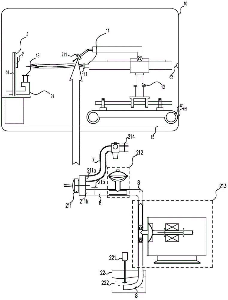
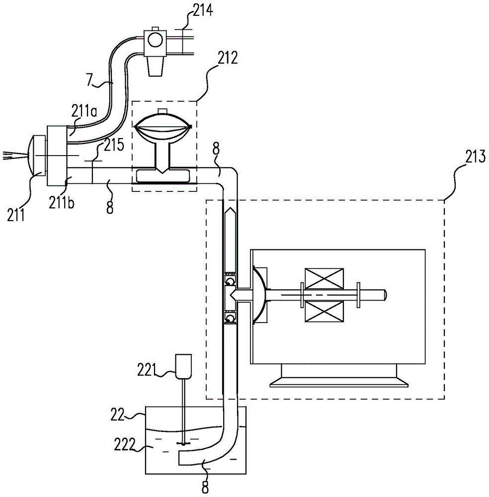
Test apparatus for thermal shock life evaluation of thermal barrier coating
A technology of thermal barrier coating and evaluation test, which is applied in measurement devices, instruments, scientific instruments, etc., to achieve the effect of convenient data query, quick operation and friendly man-machine interface
- Summary
- Abstract
- Description
- Claims
- Application Information
AI Technical Summary
Problems solved by technology
Method used
Image

Examples
application example 1
[0100] The sample thermal barrier coating was sprayed by atmospheric plasma, and the coating thickness was 250 μm. The front side of the sample is heated to 1200°C, and the cooling temperature on the back side is kept at 900°C for 5 minutes. During the CMAS coupling test, the liquid material delivery flow rate is 10LPM, the compressed air pressure is 0.04MPa, and the CMAS suspension concentration is 0.1%. After 107 coupling tests, the surface of the sample had obvious deposition of CMAS substances, and at the same time, the surface of the sample had obvious coating peeling, and the peeling area reached 20% of the surface coating, and part of the bonding layer was exposed.
application example 2
[0102] The sample thermal barrier coating was sprayed by supersonic plasma, and the thickness of the coating was 250 μm. The front side of the sample is heated to 1200°C, and the cooling temperature on the back side is kept at 900°C for 5 minutes. During the CMAS coupling test, the liquid material delivery flow rate is 10LPM, the compressed air pressure is 0.04MPa, and the CMAS suspension concentration is 1%. After 20 coupling cycles, there were obvious CMAS deposits on the surface of the sample, but the coating did not fail. After 31 coupling tests, the coating in the central area had obvious CMAS deposition, and part of the coating peeled off. fail.
application example 3
[0104] The sample thermal barrier coating is supersonic plasma sprayed, and the coating thickness is 250 μm. The front side of the sample is heated to 1200°C, and the cooling temperature on the back side is kept at 900°C for 5 minutes. During the CMAS coupling test, the liquid material delivery flow rate is 10LPM, the compressed air pressure is 0.04MPa, and the CMAS suspension concentration is 1%. After 20 coupling cycles, there is a small amount of CMAS deposits on the surface of the sample. After 60 tests, the coating in the central area of the sample has obvious CMAS deposition. After 82 tests, the coating in the central area is obviously peeled off, and there are CMAS substances Deposit again on flaking areas.
PUM
 Abstract
Description
Claims
Application Information