Visible nanometer anti-counterfeit label
An anti-counterfeit label, nano-technology, applied in the field of nano-anti-counterfeit labels visible to the naked eye, can solve the problems of easy anti-manufacturing and inconvenient application, and achieve the effects of promoting development, improving colloidal stability, and improving mechanical stability
- Summary
- Abstract
- Description
- Claims
- Application Information
AI Technical Summary
Problems solved by technology
Method used
Image

Examples
Embodiment 1
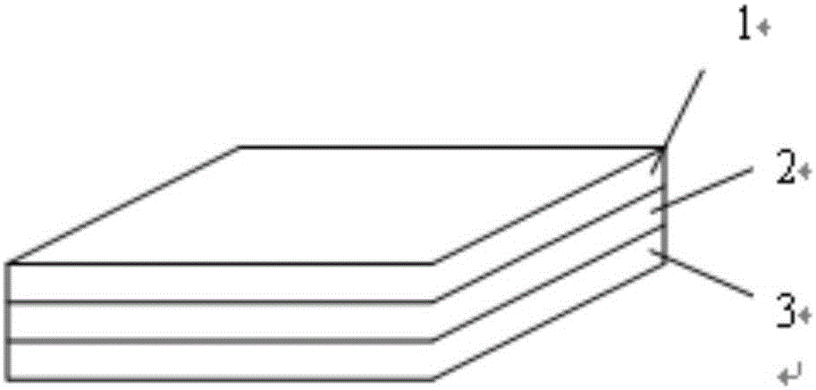
[0030] Such as figure 1 As shown, a naked eye visible nanometer anti-counterfeit label is an anti-counterfeit confirmation mark that can be directly seen by the naked eye. The label includes a composite refraction lens layer (1), a focal length layer (2) and an image mode layer (3). The composite refraction lens layer (1) is connected to the focal length layer (2), and the focal length layer is connected to the image mode layer (3); the lenses of the composite refraction lens layer (1) are arranged by a grating cross and a surface plane The composition of the processing coating, the lens is a square lens; the composition material of the image mode layer (3) includes nanoparticles, and the image mode layer (3) is a 3D structure composed of the nanoparticles, and the 3D structure is Letter; the nanoparticle is a particle with a core and shell structure, and the shell is made of silica material; the diameter of the core is 15nm, and the thickness of the shell is 8nm; the voids of...
Embodiment 2
[0038] Such as figure 1 As shown, a naked eye visible nanometer anti-counterfeit label can be directly visible with the naked eye to confirm the anti-counterfeit mark. The composite refraction lens layer (1) is connected to the focal length layer (2), and the focal length layer is connected to the image mode layer (3); the lenses of the composite refraction lens layer (1) are arranged by gratings crossing and surface Plane treatment coating composition, the lens is a square lens; the composition material of the image mode layer (3) includes nanoparticles, the image mode layer (3) is a 3D structure composed of the nanoparticles, and the 3D structure is a symbol; the nanoparticle is a particle with a core and shell structure, and the shell is made of a silica material; the diameter of the core is 15nm, and the thickness of the shell is 28nm; in the void of the nanoparticle Filled with epoxy resin.
[0039] The method and function of filling epoxy resin in the gaps of the above...
Embodiment 3
[0046] Such as figure 1 As shown, a naked eye visible nanometer anti-counterfeit label can be directly visible with the naked eye to confirm the anti-counterfeit mark. The composite refraction lens layer (1) is connected to the focal length layer (2), and the focal length layer is connected to the image mode layer (3); the lenses of the composite refraction lens layer (1) are arranged by gratings crossing and surface Plane treatment coating composition, the lens is a square lens; the composition material of the image mode layer (3) includes nanoparticles, the image mode layer (3) is a 3D structure composed of the nanoparticles, and the 3D structure is a mark; the nanoparticle is a particle with a core and shell structure, and the shell is made of silica material; the diameter of the core is 15nm, and the thickness of the shell is 20nm; Filled with epoxy resin.
[0047] The method and function of filling epoxy resin in the gaps of the above-mentioned nanoparticles are as foll...
PUM
| Property | Measurement | Unit |
|---|---|---|
| Diameter | aaaaa | aaaaa |
| Thickness | aaaaa | aaaaa |
| Thickness | aaaaa | aaaaa |
Abstract
Description
Claims
Application Information