Radiating bracket for placing cylindrical batteries in cylindrical battery pack

A cylindrical battery and heat dissipation bracket technology, applied in battery pack components, secondary batteries, circuits, etc., can solve problems such as affecting battery life, difficult to monitor battery temperature, and inability to effectively take away battery heat, to prevent heat accumulation. Effect

Inactive Publication Date: 2016-08-17
NANJING SKYSOURCE POWER TECH CO LTD
View PDF7 Cites 10 Cited by
  • Summary
  • Abstract
  • Description
  • Claims
  • Application Information

AI Technical Summary

Problems solved by technology

Air cooling, natural cooling, etc. are generally used for battery heat dissipation. Due to the complex internal chemical reactions of the battery during charging and discharging, accompanied by heat generation, especially for devices composed of multiple battery cells, such a small The arrangement with dense gaps is easy to form heat accumulation in the middle, the heat of the middle battery itself cannot be effectively dissipated, and the temperature inside the battery is difficult to monitor, resulting in thermal runaway.
[0003] Not only that, after the batteries are connected in series and parallel, due to the limitation of the assembly of the module module itself, the connection method of the cylindrical battery also occupies most of the area of ​​the battery itself, which means that there are very few battery gaps reserved by itself. Or the intermediate battery cannot get an effective heat dissipation environment, and the heat of the battery itself cannot be effectively taken away after the fan is installed. When the temperature of the battery is different during use, it will cause inconsistencies in the whole box of batteries, thus affecting the service life of the entire battery pack. , and leave a security risk

Method used


Image

  • Radiating bracket for placing cylindrical batteries in cylindrical battery pack
  • Radiating bracket for placing cylindrical batteries in cylindrical battery pack
  • Radiating bracket for placing cylindrical batteries in cylindrical battery pack

Examples


Embodiment Construction

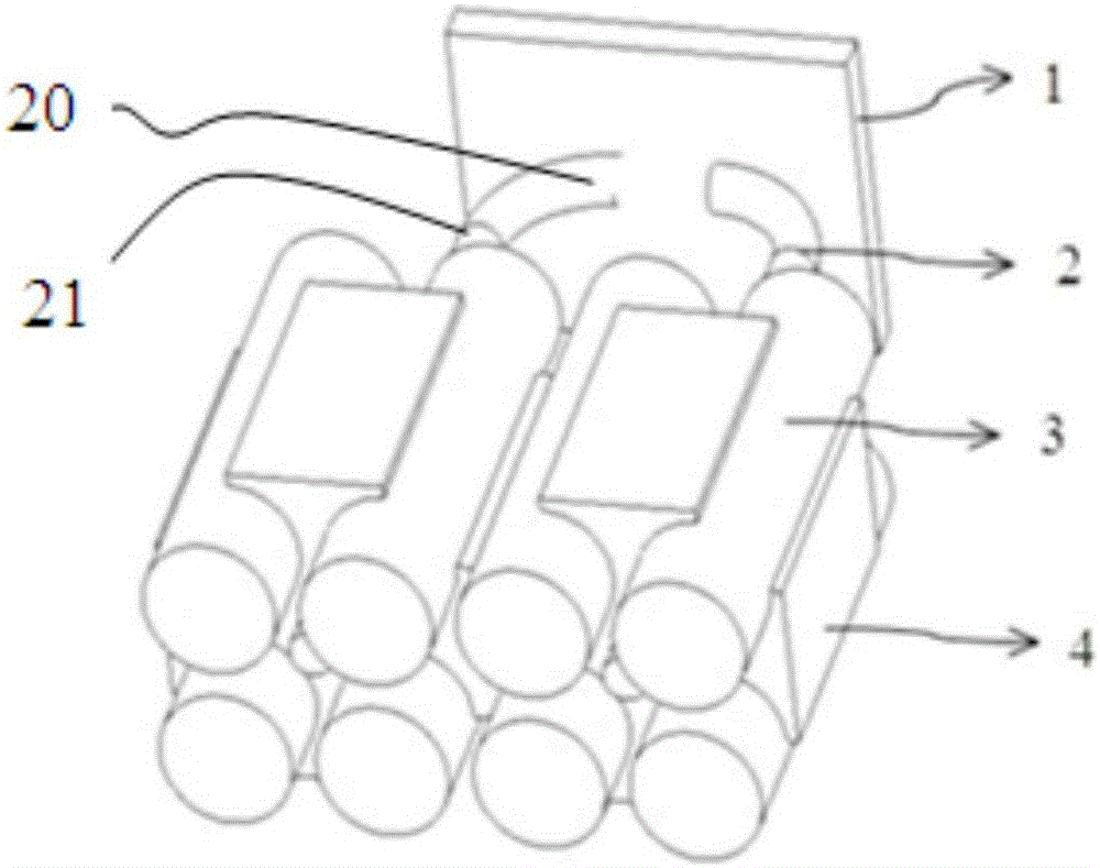
[0021] Such as figure 1 As shown, the cylindrical battery pack of the present invention includes an aluminum substrate 1 , a heat pipe 2 , a cylindrical battery 3 and a cooling bracket 4 . The shape of the cylindrical battery 3 is cylindrical, the outer layer is wrapped by an insulating film, and the two ends are positive tabs and negative tabs respectively. The heat dissipation bracket 4 is made of industrial pure aluminum, which not only has good thermal conductivity but also has certain hardness.

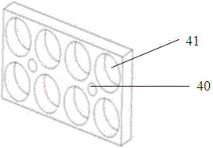
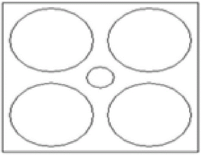
[0022] The cooling bracket 4 is provided with a through hole 40, the extension direction of the through hole 40 is consistent with the extension direction of the cylindrical battery 3, and a positioning part 41 for placing the cylindrical battery 3 is formed around the through hole 40. The role of the positioning part 41 is as follows: The purpose is to position the cylindrical battery 3 , and the second is that the heating surface of the cylindrical battery 3 is in close contac...


PUM


Abstract

The invention discloses a radiating bracket for placing cylindrical batteries in a cylindrical battery pack. The shapes of the cylindrical batteries are cylindrical; the outer layer of each cylindrical battery is coated with an insulating film; a positive tab and a negative tab are respectively formed at the two tail ends of each cylindrical battery; through holes are formed in the radiating bracket; the extending direction of the through holes is consistent with that of the cylindrical batteries; positioning parts which are used for holding the cylindrical batteries are formed on the periphery of each through hole. According to the radiating bracket disclosed by the invention, good radiating environment is provided for the cylindrical batteries; the heat generated when the cylindrical batteries are charged or discharged can be absorbed quickly by the radiating bracket; the accumulation of the heat on the surfaces of the cylindrical batteries is prevented; meanwhile, a fixing action is also added to the cylindrical batteries; the radiating bracket can be matched according to a single cylindrical battery or a plurality of the cylindrical batteries; different lengths and different surfaces can also be selected according to different charge-discharge rates of the batteries.

Description

Technical field: [0001] The invention relates to a cooling support for placing cylindrical batteries in a cylindrical battery pack, which belongs to the technical field of batteries. Background technique: [0002] Most of the existing cylindrical battery packs are used after multiple batteries are connected in series and parallel. In electric vehicles and energy storage systems, high-voltage and high-capacity battery packs are required. Coupled with the series-parallel relationship between the positive and negative electrodes, the gap between the batteries is very small. Air cooling, natural cooling, etc. are generally used for battery heat dissipation. Due to the complex internal chemical reactions of the battery during charging and discharging, accompanied by heat generation, especially for devices composed of multiple battery cells, such a small The arrangement with dense gaps is easy to form heat accumulation in the middle, the heat of the middle battery itself cannot b...

Claims


Application Information

Patent Timeline
Patent Type & Authority Applications(China)
IPC IPC(8): H01M2/10H01M10/613H01M10/643H01M10/655H01M50/213H01M50/256
CPCH01M10/613H01M10/643H01M10/655H01M50/256H01M50/213Y02E60/10
Inventor 王中玉黄永辉
Owner NANJING SKYSOURCE POWER TECH CO LTD
Why Eureka
Try Eureka