Inter-rack technical roller replacement device and method

A technology between process rolls and stands, which is applied in the direction of metal rolling stands, manufacturing tools, metal rolling mill stands, etc., can solve the problems of smashing people and stand equipment, low operating efficiency, and high labor intensity, and achieves a solution damage, increase operating rate, and reduce labor intensity

Inactive Publication Date: 2016-08-24
ANGANG STEEL CO LTD
View PDF6 Cites 6 Cited by
  • Summary
  • Abstract
  • Description
  • Claims
  • Application Information

AI Technical Summary

Problems solved by technology

There are illegal lifting operations during the operation, people standing on the support rollers are easy to slip and fall
Binding new rollers with steel ropes is very easy to cause damage to the roller surface, and once the stee

Method used


Image

  • Inter-rack technical roller replacement device and method
  • Inter-rack technical roller replacement device and method

Examples


Example Embodiment

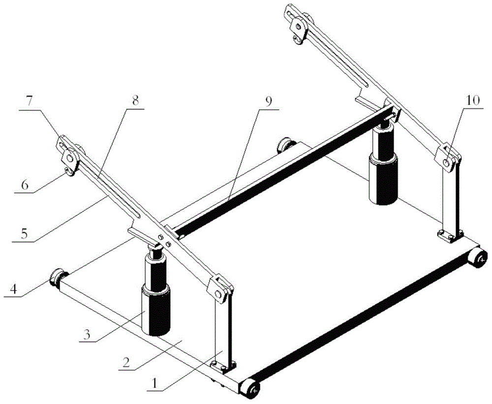
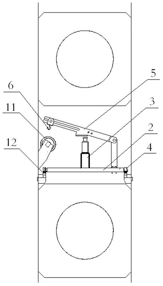
[0020] Depend on figure 1 It can be seen that the inter-frame process roll replacement device of the present invention is mainly composed of a pull plate 1, a trolley 2, a jack 3, an arm 5, a hook 6, a slide block 7, a crossbeam 9 and a bearing pin 10. The trolley 2 is a rectangular flat plate, and the four corners of the trolley 2 are respectively equipped with rail wheels 4. The two sides of the upper surface of the trolley 2 are respectively fixed with a pull plate 1 by bolts, and one end of the hanging arm 5 is hinged with a pin 10. At the upper end of the pull plate 1, the middle parts of the two hanging arms 5 are connected together by a cross beam 9, and the two ends of the cross beam 9 are connected to the middle parts of the two hanging arms 5 with bolts respectively. The other side of the hanging arm 5 is provided with a chute 8 respectively, and a slide block 7 is slidably connected in the chute 8, and a hook 6 is provided below the slide block 7; There is a backin...


PUM


Abstract

Provided are an inter-rack technical roller replacement device and method. The inter-rack technical roller replacement device is composed of pulling boards, a mobile trolley, jacks, hanger arms, hooks, sliding blocks, a cross beam and hinge pins. The pulling boards are arranged on the two sides of the mobile trolley. The hanger arms are hinged to the pulling boards, and a sliding slot is formed in the other side of each hanger arm. The sliding blocks with the hooks are connected to the interiors of the sliding slots in a sliding mode. Each jack is arranged under the corresponding hanger arm. A roller replacement trolley track and an inner track of a machine frame are connected. A crane is used for placing the mobile trolley on the roller replacement trolley track to be fed into a leveling machine frame; the jacks are utilized for jacking up the hanger arms after the hanger arms, the cross beam and the jacks are installed in positions; a technical roller slips to the roots of the sliding slots; the jacks are descended so that the technical roller can be placed on the mobile trolley; and then the technical roller is conveyed to a roller replacement trolley outside the leveling machine frame by the mobile trolley. Installation of a new technical roller can be completed by carrying out contrary operations. By means of the inter-rack technical roller replacement device and method, personal accidents and equipment accidents can be avoided, the roller replacement time can be shortened, the labor intensity is relieved, the shutdown loss is reduced, the unit operation rate is increased, and the roller surfaces are effectively prevented from being damaged.

Description

technical field [0001] The invention belongs to the field of mechanical equipment, and in particular relates to a device and method for changing process rolls between frames of a cold-rolling leveling and skin-passing unit. Background technique [0002] In order to prevent strip shaking, wrinkling and steel plate folding during high-speed production in the skin pass unit and skin pass unit of the cold rolling mill, two process rolls, an anti-wrinkle roll and an anti-jump roll, are installed in the frame. However, when changing anti-wrinkle rollers or anti-jumping rollers, because there is no working surface and the space is small, people stand on the support rollers to work each time the rollers are changed, and the rollers are tied up with steel ropes and then hoisted from multiple directions by multiple manual hoists. The upward resultant force formed by the oblique pull can lift the process roller. When transporting the old roll out of the frame, it is necessary to use a...

Claims


Application Information

Patent Timeline
IPC IPC(8): B21B31/08B21B31/12
Inventor 曹威孙长津
Owner ANGANG STEEL CO LTD
Why Eureka
Try Eureka