A kind of metal tube surface heat treatment equipment

A surface heat treatment, metal tube technology, applied in heat treatment equipment, heat treatment furnaces, furnaces, etc., can solve the problem of reduced toughness, difficult to meet the refinement requirements of medical small metal tubes, thin tube water droplet structure and cleanliness It is difficult to meet the surgical grade, etc. question

Active Publication Date: 2018-07-24
SHENZHEN MUCHUAN ELECTROMECHANICAL EQUIP CO LTD
View PDF6 Cites 0 Cited by
  • Summary
  • Abstract
  • Description
  • Claims
  • Application Information

AI Technical Summary

Problems solved by technology

The current heat treatment technology cannot repair the fine scratches on the stretched surface of the thin tube metal, such as: 1. The heating wire is used to radiate, the speed is slow, and the heat transfer efficiency is slow, which will easily lead to changes in the crystal structure of the fine metal tube. The physical properties of the thin tube are changed to reduce its toughness; 2. The surface water droplet structure and cleanliness of the thin tube are difficult to meet the requirements of the surgical grade when heated by immersion; Although the method avoids the disadvantages caused by the above two methods, because the stretched lines are in a compressed state, when the heat treatment fills the pits of the lines, there will be cases of overfilling and causing fine bulges.
Therefore, the above traditional heat treatment methods are difficult to meet the refinement requirements of the surface heat treatment methods of medical fine metal tubes

Method used


Image

  • A kind of metal tube surface heat treatment equipment
  • A kind of metal tube surface heat treatment equipment
  • A kind of metal tube surface heat treatment equipment

Examples


Embodiment Construction

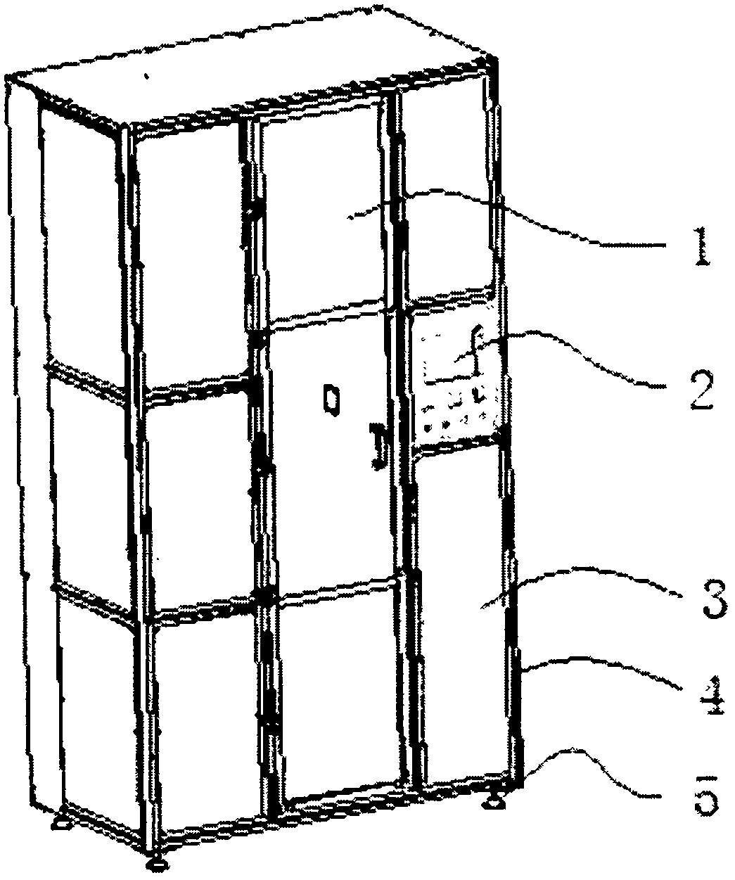
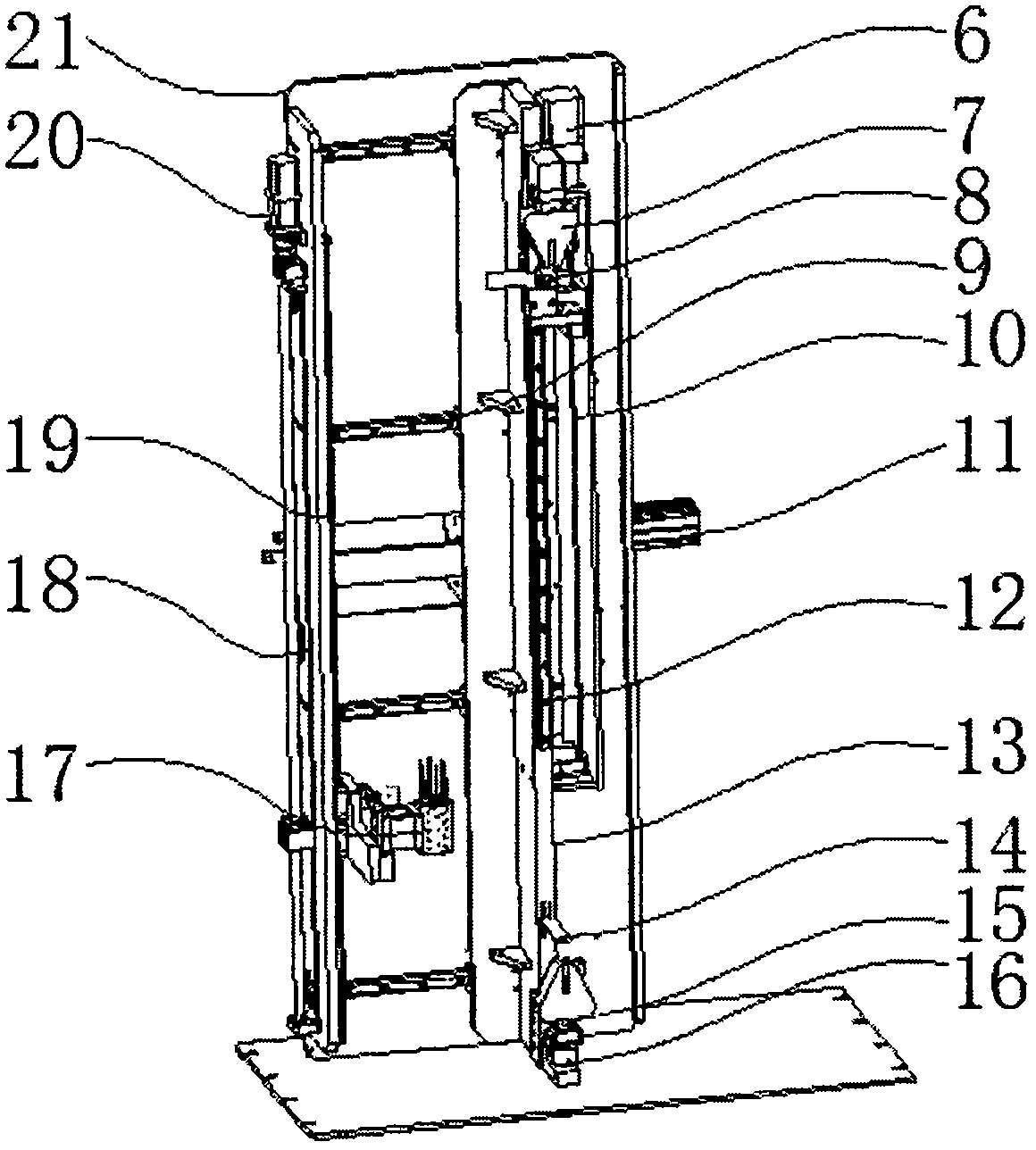
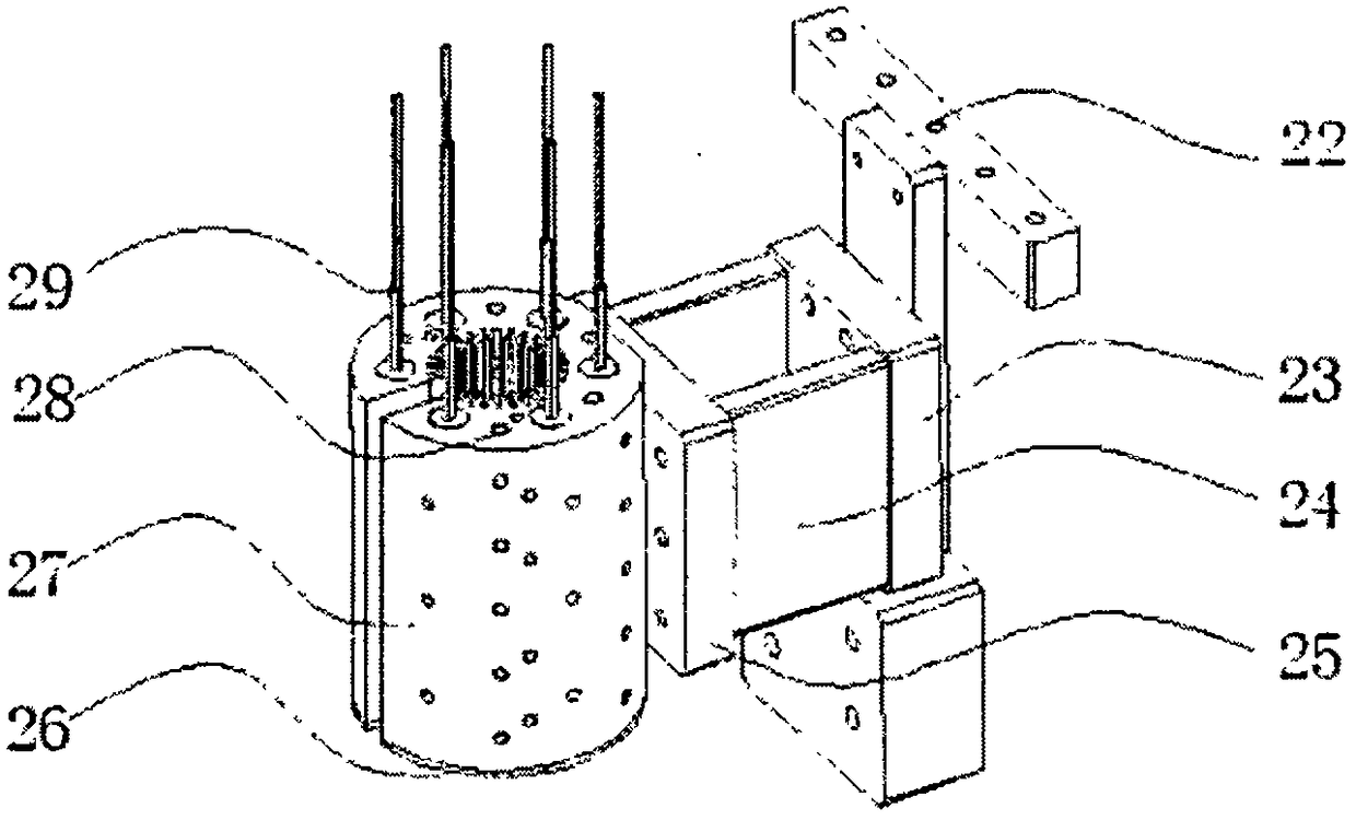
[0019] The following will be combined with figure 1 to attach Figure 4 The present invention is described further with embodiment, but should not limit protection scope of the present invention with this.

[0020] The invention provides a metal tube surface heat treatment equipment, which includes an equipment frame, a body structure arranged in the frame for supporting the metal pipe, a heating body structure arranged on one side of the body structure for heating the metal pipe, and an electric A control module connecting the body structure and the heating body structure for controlling the relative movement of the body structure and the heating body structure.

[0021] as attached figure 1 As shown, the front panel of the equipment rack includes a safety door 1 for replacing metal pipes, a side wall for placing an electric control box 3 for a control module, and an operation panel 2 for electrically connecting the control module; the equipment The bottom surface of the f...


PUM


Abstract

The invention discloses heat treating equipment for surfaces of a metal pipe, and belongs to the field of heat treating equipment for medical appliance materials. The heat treating equipment comprises a machine frame of the equipment, a machine body structure, a heating body structure and a control module, wherein the machine body structure is arranged in the machine frame to be used for supporting the metal pipe; the heating body structure is arranged on one side of the machine body structure to be used for heating the metal pipe; the control module is electrically connected with the machine body structure and the heating body structure to be used for controlling the relative movement of the machine body structure and the heating body structure. According to the heat treating equipment for the surfaces of the metal pipe, the metal pipe is clamped by the machine body structure which is used for supporting the metal pipe; the heating body structure on one side moves relative to the machine body structure, so that the metal pipe on the machine body structure is heated in a stretching manner, and sterile operation on the metal pipe during a stretching process is guaranteed; under the condition that the physical characteristics of the metal pipe are not changed, smoothing treatment in a water droplet manner is performed on stretching traces on the surfaces of the metal pipe. The heat treating equipment provided by the invention is simple in structure, and besides, refinement requirements of medical appliances for thin metal pipes are met.

Description

technical field [0001] The invention relates to the field of heat treatment equipment for medical device materials, in particular to a metal tube surface heat treatment equipment. Background technique [0002] In the process of producing fine metal tubes by stretching method, there will be slight stretch marks, and the fine metal tubes are mostly used in medical operations, and fine stretch marks will cause adverse reactions in the internal tissues of the human body. Therefore, it is necessary to carry out the surface inspection of the fine metal tubes. Water droplet treatment. The current heat treatment technology cannot repair the fine scratches on the stretched surface of the thin tube metal, such as: 1. The heating wire is used to radiate, the speed is slow, and the heat transfer efficiency is slow, which will easily lead to changes in the crystal structure of the fine metal tube. The physical properties of the thin tube are changed to reduce its toughness; 2. The surfa...

Claims


Application Information

Patent Timeline
Patent Type & Authority Patents(China)
IPC IPC(8): B21C1/22C21D8/10C21D9/08
CPCB21C1/22C21D8/10C21D9/08
Inventor 郭冰勋蔡文勇
Owner SHENZHEN MUCHUAN ELECTROMECHANICAL EQUIP CO LTD
Why Eureka
Try Eureka