
a rotary table

A technology of rotary table and slide table, applied in the direction of manufacturing tools, other manufacturing equipment/tools, etc., can solve problems such as affecting the production efficiency and quality of PCD/CBN tools, raising the threshold, etc., to achieve flexibility, motion accuracy and The effect of improving stability and reducing skill requirements

Active Publication Date: 2018-12-04
BEIJING DEMINA PRECISION MACHINERY
View PDF6 Cites 0 Cited by
  • Summary
  • Abstract
  • Description
  • Claims
  • Application Information

AI Technical Summary

Problems solved by technology

On a general PCD / CBN tool grinding machine, the movement of the rotary table is manually controlled by the operator, and the coordinated operation of both hands puts forward high requirements on the operator's skill level. This requirement raises the threshold for entering this industry and seriously Affect the production efficiency and quality of PCD / CBN tools

Method used


Image

  • a rotary table
  • a rotary table

Examples


Embodiment Construction

[0012] The present invention will be further described below with reference to the accompanying drawings and specific embodiments.

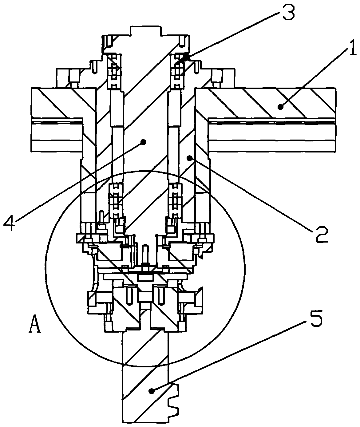
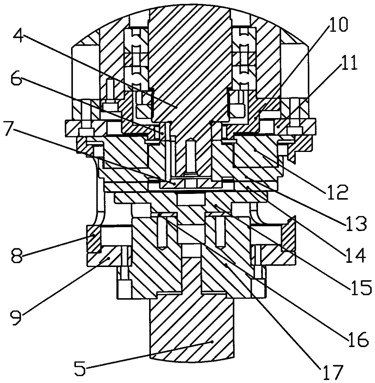
[0013] Such as figure 1 and figure 2 Shown: a rotary table according to an embodiment of the present invention, including a feed slide 1, one side of the feed slide 1 is provided with a cylindrical convex part with a through hole inside, and a vertical shaft 4 is provided in the through hole , the vertical shaft 4 is provided with a vertical shaft sleeve 2, and the two ends between the vertical shaft 4 and the vertical shaft sleeve 2 are respectively provided with a bearing group 3, the bearing group 3 is a high-precision bearing group, and the vertical shaft 4 The lower end is provided with a reducer 17 and a servo motor 5 in turn, the servo motor 5 is arranged at the lower end of the reducer 17, the lower end of the vertical shaft sleeve 2 is provided with a lower end cover 10, and the vertical shaft 4 runs through the lower end cover 10 , a...


PUM


Abstract

The invention relates to a rotary workbench. The rotary workbench comprises a feeding sliding table. A cylinder protruding portion internally provided with a through hole is arranged on one side of the feeding sliding table. A vertical shaft is arranged in the through hole and sleeved with a vertical shaft sleeve. Bearing sets are arranged at the two ends of the portion between the vertical shaft and the vertical shaft sleeve. A reducer and a servo motor are sequentially arranged at the lower end of the vertical shaft. The servo motor is arranged at the lower end of the reducer. A lower end cover is arranged at the lower end of the vertical shaft sleeve. The vertical shaft penetrates the lower end cover. An inner spacer bush is arranged between the lower end of the vertical shaft and the lower end cover. A transition plate is arranged at the lower end of the protruding portion. The tail end of the vertical shaft is sleeved with a clutch stator and a clutch rotor which are matched with each other. A clutch armature is arranged below the clutch rotor and connected with the reducer through an armature connecting disc. An adjusting pad is arranged between the armature connecting disc and the reducer. A gland is arranged in the center of the end of the vertical shaft. The rotary workbench has the beneficial effects that the rotary workbench is simple in structure, safe and reliable in operation and convenient to operate.

Description

technical field [0001] The invention relates to a rotary worktable. Background technique [0002] The rotary motion of the rotary table of the PCD / CBN tool grinder determines the precision and cutting edge quality of the ground tool, so the precision and stability of the motion are very important. On a general PCD / CBN tool grinding machine, the movement of the rotary table is manually controlled by the operator, and the coordinated operation of both hands puts forward high requirements on the operator's skill level. This requirement raises the threshold for entering this industry and seriously Affect the production efficiency and quality of PCD / CBN tools. Contents of the invention [0003] In view of the above-mentioned problems in the prior art, the main purpose of the present invention is to solve the defects of the prior art. The present invention provides a rotary table with simple structure, safe and reliable operation and convenient operation. [0004] The inventio...

Claims


Application Information

Patent Timeline
Patent Type & Authority Patents(China)
IPC IPC(8): B24B3/00
Inventor 王志晟潘伟光黄广智
Owner BEIJING DEMINA PRECISION MACHINERY
Learn More