Microthruster chip of microsatellite

A technology of micro-thrusters and micro-satellites, which is applied in the field of micro-thruster chips of micro-satellites, can solve the problems of slow temperature rise and heat consumption inside the heating chamber, and achieve high manufacturing costs, long manufacturing cycles, and acid and alkali resistance of vapor pressure Effect

Inactive Publication Date: 2016-08-24
SHANGHAI ENG CENT FOR MICROSATELLITES
View PDF4 Cites 3 Cited by
  • Summary
  • Abstract
  • Description
  • Claims
  • Application Information

AI Technical Summary

Problems solved by technology

The heating wire is placed outside the heating chamber so that the temperature inside the heating chamber rises slowly and causes a certain amount of heat consumption

Method used


Image

  • Microthruster chip of microsatellite
  • Microthruster chip of microsatellite
  • Microthruster chip of microsatellite

Examples


Embodiment Construction

[0023] The present invention will be described in detail below in conjunction with the accompanying drawings. This embodiment is carried out on the premise of the technical solution of the present invention, and detailed implementation and specific operation process are given, but the protection scope of the present invention is not limited to the following embodiments.

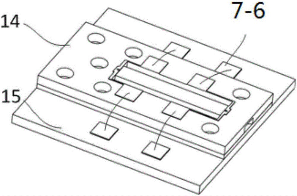
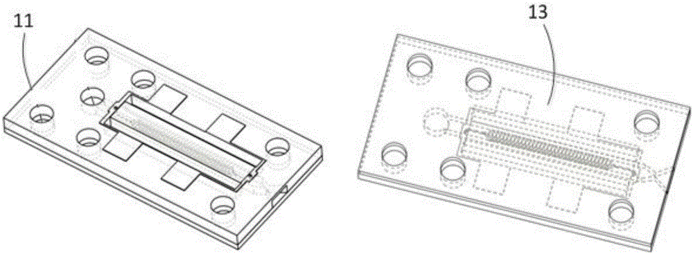
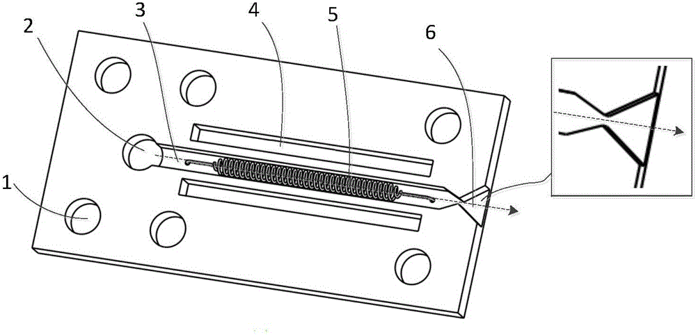
[0024] Such as Figure 2 to Figure 4 As shown, a micro-propulsion chip of a tiny satellite comprises a heating cavity 3, a heating wire 5 is provided in the heating cavity 3, and an extraction hole 17 is provided on the heating cavity 3 wall so that the two ends of the heating wire 5 are separated from the heating cavity. 3 lead out to the outside of the heating chamber 3. The heating wire 5 is placed outside the heating chamber 3 so that the heating speed inside the heating chamber 3 is slow and causes a certain amount of heat consumption. The heating wire 5 is placed inside the heating chamber 3 so that t...


PUM


Abstract

The invention relates to a microthruster chip of a microsatellite. The microthruster chip comprises a heating cavity (3) and is characterized in that a heating wire (5) is arranged in the heating cavity (3), and lead-out holes (17) are formed in the wall of the heating cavity (3) so as to enable two ends of the heating wire (5) to be led out of the heating cavity (3) from the heating cavity (3).

Description

technical field [0001] The invention relates to a micro-propeller for a micro-satellite, in particular to a micro-propulsion chip for a micro-satellite. Background technique [0002] Microsatellites have the characteristics of small size, light weight, low cost, short production cycle, and wide application fields, which makes the aerospace departments of various countries attach great importance to the development of microsatellite technology. Most satellites use a propulsion system for orbit control and attitude adjustment. As the volume of satellites is increasingly miniaturized, the technical requirements for the propulsion system are more stringent, leading to the development of satellite thruster technology. The small size and light weight of microsatellites make their moments of inertia small. It is possible to control the attitude of the micro-satellite or keep the micro-satellite running on the set orbit by using a small thrust; however, only when the probability o...

Claims


Application Information

Patent Timeline
Patent Type & Authority Applications(China)
IPC IPC(8): F02K9/60B64G1/40
CPCF02K9/60B64G1/401
Inventor 康宝鹏李昭赵学聪张传鑫吴树范陈雯
Owner SHANGHAI ENG CENT FOR MICROSATELLITES
Why Eureka
Try Eureka