

High-efficiency three-ring fire burner and gas stove
A burner and ring fire technology, applied in the direction of burners, gas fuel burners, combustion methods, etc., can solve the problems of small heat exchange time and heat exchange area, lower pot heat utilization rate, and large burner volume, etc., to achieve Larger heat transfer time and heat transfer area, improved firepower and thermal efficiency, and reduced head volume
- Summary
- Abstract
- Description
- Claims
- Application Information
AI Technical Summary
Problems solved by technology
Method used
Image

Examples
Embodiment Construction
[0023] The specific implementation manners of the present invention will be further described in detail below in conjunction with the accompanying drawings.
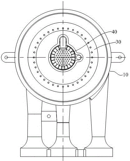
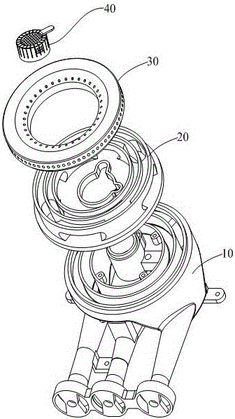
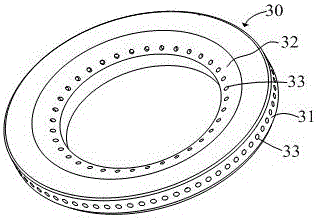
[0024] refer to Figure 1 to Figure 6 , a high-efficiency three-ring fire burner, including a furnace head 10, a gas distribution plate 20, an inner ring wall 31 and an outer ring wall 32 with an outer fire cover 30 with a fire outlet 33 and a center with a central fire hole 41 The fire cover 40, the gas distribution plate 20 includes a central gas passage 21 corresponding to the central fire cover 40 and an outer ring gas passage 22 corresponding to the outer fire cover 30; An annular separating rib 34 is arranged between to separate the gas chamber of the outer fire cover 30 into a middle ring fire gas chamber 35 and an outer ring fire gas chamber 36; The partition ring 23 corresponding to the rib 34 separates the outer ring gas passage 22 into a middle ring fire gas passage 221 corresponding to the middle ring fire g...
PUM
| Property | Measurement | Unit |
|---|---|---|
| Diameter | aaaaa | aaaaa |
Abstract
Description
Claims
Application Information