Supercharge Your Innovation With Domain-Expert AI Agents!

Microwave induction antenna module

An antenna module, microwave induction technology, applied in radio wave measurement systems, radio wave reflection/re-radiation, instruments, etc., to improve lighting effects, reduce consumables, and take into account lighting effects and induction efficiency.

Active Publication Date: 2019-02-26
LIVINGSTYLE ENTERPRISES LTD
View PDF9 Cites 0 Cited by
  • Summary
  • Abstract
  • Description
  • Claims
  • Application Information

AI Technical Summary

Problems solved by technology

[0010] Generally speaking, a number of micro-strip lines (Micro-strip) on one side of the substrate used in the antenna module 154b are directly printed and formed with strip-shaped metal wires, and these micro-strip lines include such as figure 2 When the above-mentioned oscillating circuit structure 220 or the above-mentioned detection hybrid circuit structure 250 are in the wire layout (layout) mode, the maximum side length L0 of the above-mentioned substrate often falls between 25 mm and 36 mm at least, and even if the design is poor, this size will be longer

Method used


Image

  • Microwave induction antenna module
  • Microwave induction antenna module
  • Microwave induction antenna module

Examples


Embodiment Construction

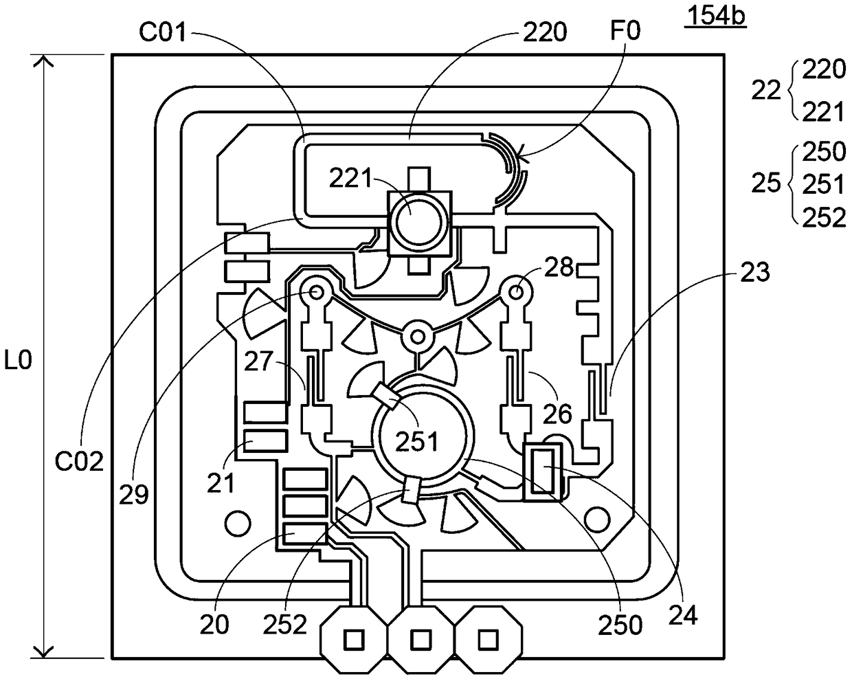
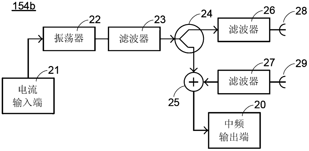
[0052] Now, a first embodiment is used to describe the implementation of the microwave induction antenna module 300 proposed by the present invention. Please also see Figure 4 with Figure 5 ,in Figure 4 is a schematic circuit diagram of the microwave induction antenna module 300 of the first embodiment, and Figure 5 Then it is a functional block diagram of the microwave induction antenna module 300 . As shown in the figure, the microwave induction antenna module 300 mainly includes a current input terminal 31, an oscillator 32, a power divider 34, a transmitting antenna 38, a receiving antenna 39, a detection mixer 35, an intermediate frequency (IF ) output 30 and a plurality of filters 33,36,37. The figure also shows the coupling relationship between the various elements, and each element is arranged on a substrate 3 having a first side 3a and a second side (not shown in the drawings). Figure 4 Only the plane on which the first side 3 a is located is shown in FIG. 2...


PUM


Abstract

A microwave sensing antenna module comprising a substrate (3), a wave detecting mixer (35), and an oscillator (32). The substrate (3) is provided with a first lateral surface (3a). The first lateral surface (3a) is provided with a first area. The oscillator (32) is provided with an oscillator circuit structure (320) and a radiofrequency transistor (321) arranged thereon within the first area. The wave detecting mixer (35) is arranged on the first lateral surface (3a) and is provided with a wave detecting mixer circuit structure (350) and at least one wave detecting component arranged thereon. The oscillator circuit structure (320) comprises multiple structural segments (S1-S4). The structural segments (S1-S4) each comprise a curved part (C1-C4). Some of the structural segments (S1-S4) of the oscillator circuit structure (320) are connected to each other and some of the curved parts (C1-C4) are curved in the direction of the first area to be in proximity with or retracted from each other, thus greatly reducing the area to be occupied by the circuit layout. The microwave sensing antenna module is capable of reducing the overall size while ensuring effective microwave sensing.

Description

technical field [0001] The invention relates to a microwave induction antenna module, in particular to a microwave induction antenna module applied to an illuminating device. Background technique [0002] Ordinary lighting devices or lamps use traditional incandescent bulbs, lamp tubes or energy-saving bulbs as light-emitting elements to provide lighting, and most of the conventional control methods are to artificially control the flickering of these light-emitting elements. With the advancement of technology, the design of light-emitting diodes (LEDs) as light-emitting elements is becoming more and more widespread, and brings higher lighting effects. In addition, currently, the lighting device or lamp designed by using the motion sensing technology to control the flickering of the light-emitting element can more effectively achieve the purpose of saving energy. [0003] The so-called motion sensing technology is to install a sensor in the lighting device or lamp, which can...

Claims


Application Information

Patent Timeline
Patent Type & Authority Patents(China)
IPC IPC(8): G01S13/88G01S7/02
CPCG01S7/02G01S13/88
Inventor 陈明允洪盛国
Owner LIVINGSTYLE ENTERPRISES LTD
Features
  • R&D
  • Intellectual Property
  • Life Sciences
  • Materials
  • Tech Scout
  • Unparalleled Data Quality
  • Higher Quality Content
  • 60% Fewer Hallucinations
Learn More