Current extraction device for aluminium base flexible conductive backboard

A conductive backplane, aluminum-based flexible technology, applied in the field of solar cells, can solve the problems of inability to weld on the surface of aluminum foil, reduce the manufacturing cost of solar back contact components, reduce the manufacturing cost of solar back contact components, etc., so as to improve market competitiveness, The effect of convenient implementation and lower production cost

Inactive Publication Date: 2016-08-24
山东拜科通新材料科技有限公司
View PDF5 Cites 5 Cited by
  • Summary
  • Abstract
  • Description
  • Claims
  • Application Information

AI Technical Summary

Problems solved by technology

[0005] The present invention aims at the above deficiencies, and the present invention provides a current extraction device for an aluminum-based flexible conductive backplane, which establishes an electrical connection between the aluminum foil and the conductive strip through electrode extraction cluster points, and solves the problems caused by the oxide layer of the aluminum foil backplane. The problem of being unable to weld with the conductive tape due to the existence of aluminum foil has made it a reality to successfully replace copper foil with aluminum foil, which greatly reduces the manufacturing cost of solar back contact components
[0007] Due to the design of the electrode lead-out cluster points deposited by supersonic cold spraying technology in each containing through hole, the conductive strips are welded on the electrode lead-out cluster points, which solves the problem that the surface of the aluminum foil cannot be welded; at the same time, due to the design of solar energy A number of receiving through hole

Method used


Image

  • Current extraction device for aluminium base flexible conductive backboard

Examples


Example Embodiment

[0014] The present invention will be described in detail below with reference to the drawings and specific embodiments:

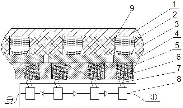
[0015] Such as figure 1 Shown is a specific embodiment of the present invention, including the solar cell layer 1, the insulating adhesive film layer 3, the aluminum foil conductive layer 4 and the solar cell back sheet film layer 5 laminated in sequence by high-temperature vacuum pressure. A number of conductive through holes 9 are opened on the insulating adhesive film layer 3, and conductive silver glue 2 is injected into each conductive through hole 9. The conductive silver glue 2 conducts the current generated by the solar cell layer 1 to the aluminum foil conductive layer 4. The solar cell backplane film layer 5 is provided with a number of receiving through holes, and in each receiving through hole, a rough surface electrode extraction cluster point 6 is formed by supersonic cold spraying technology. The supersonic cold spraying technology uses metal pa...


PUM

PropertyMeasurementUnit
Diameteraaaaaaaaaa

Abstract

The invention discloses a current extraction device for an aluminium base flexible conductive backboard. The current extraction device includes a solar battery piece layer 1, an insulation adhesive film layer 3, an aluminium foil conducting layer 4 and a solar battery backboard film layer 5, wherein the solar battery piece layer 1, the insulation adhesive film layer 3, the aluminium foil conducting layer 4 and the solar battery backboard film layer 5 are pressed together successively; a plurality of conductive through holes 9 are formed in the insulation adhesive film layer 3; conductive silver adhesives 2 are injected in each conductive through hole 9; a plurality of accommodating through holes are formed in the solar battery backboard film layer 5; an electrode extraction cluster point 6 is formed in each accommodating through hole through deposition by means of an ultrasonic cold spraying technology; a conductive belt 7 is welded on each electrode extraction cluster point 6; and the current is output to a photovoltaic conjunction box 8. For the current extraction device for an aluminium base flexible conductive backboard, electrical connection is established between the aluminium foils and the conductive belts through the electrode extraction cluster points; the problem that welding with the conductive belts cannot be realized because of existence of an aluminium foil backboard oxide layer is solved; and the aluminium foil successfully replaces a copper foil so that the manufacturing cost of a solar back contact assembly is greatly improved.

Description

technical field [0001] The invention relates to the field of solar cells, in particular to a current extraction device for an aluminum-based flexible conductive backplane. Background technique [0002] Solar back contact module technology is a new type of high-efficiency current output technology applied to photovoltaic solar cell modules. Compared with traditional solar current output technology, this technology can effectively avoid the light shielding effect of grid lines on the surface of traditional panels, It can effectively reduce the current consumption caused by the resistance of the current transmission link, and at the same time avoid the unstable quality caused by manual welding. This technology can increase the power conversion rate of solar modules by about 7%. [0003] Today's mainstream backsheet materials use copper foil as the conductive substrate. Because copper foil is expensive and the market price fluctuates greatly, it is not conducive to controlling t...

Claims


Application Information

Patent Timeline
IPC IPC(8): H01L31/02H01L31/0224H01L31/05
CPCY02E10/50H01L31/022441H01L31/0201H01L31/02013H01L31/0508H01L31/0516
Inventor 宁海洋郝学斌韩荣全朱琳
Owner 山东拜科通新材料科技有限公司
Why Eureka
Try Eureka