Reversible belt tightener

A technology of seat belt tensioner and seat belt, which is applied to belt tensioners, seat belts in vehicles, belts/chains/gears, etc., can solve the problems that the layout form cannot be freely selected, and noise can no longer be accepted, so as to achieve simplification. The effect of structure, loss reduction, and manufacturing cost reduction

Inactive Publication Date: 2016-08-24
AUTOLIV DEV AB
View PDF10 Cites 3 Cited by
  • Summary
  • Abstract
  • Description
  • Claims
  • Application Information

AI Technical Summary

Problems solved by technology

[0003] The disadvantage of this embodiment is that the arrangement of the individual components relative to one another cannot be freely selected, since the gear wheels of the transmission must each deflect the rotational movement by 90° and thus the axes of rotation of the engaging rotating components must be aligned at 90 degrees to one another. degree angle setting
In addition, it has been shown that, especially for vehicles of the highest class, car manufacturers can no longer accept the noise that develops in the crown and worm gears during belt tightening

Method used


Image

  • Reversible belt tightener
  • Reversible belt tightener
  • Reversible belt tightener

Examples


Embodiment Construction

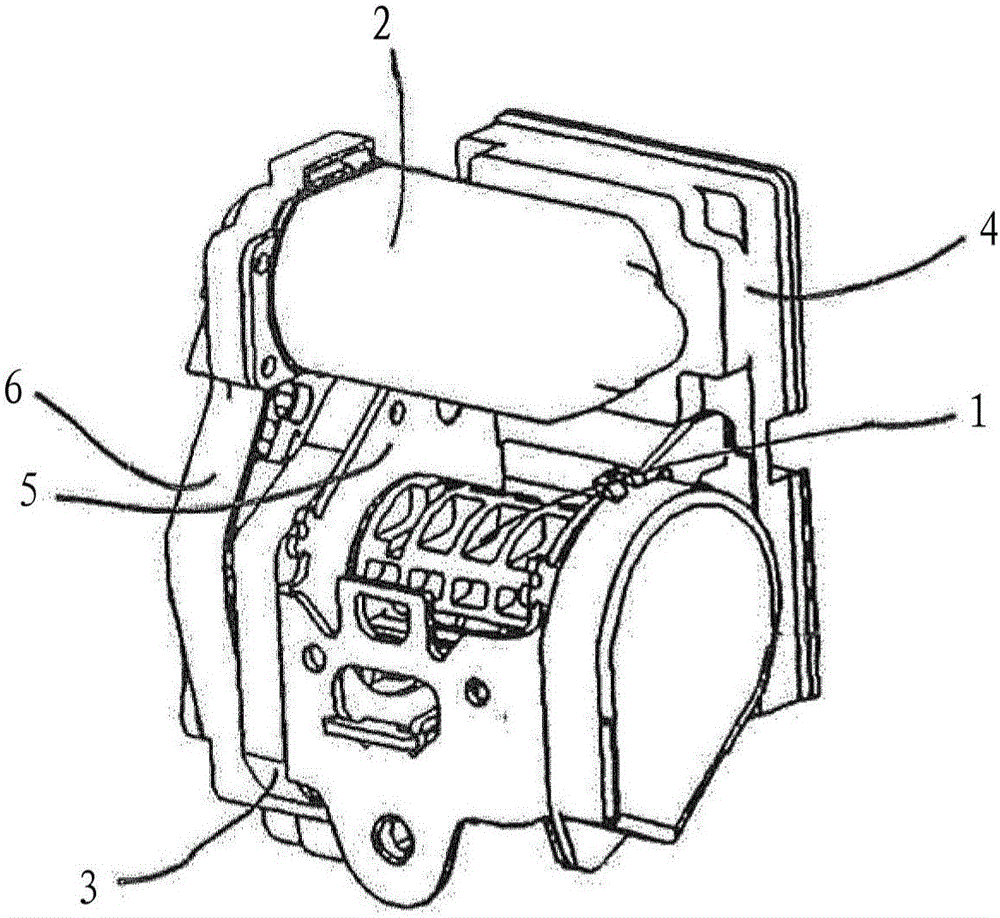
[0019] in figure 1 with figure 2 Shown therein is a reversible safety tensioner known from WO 2003 / 099619 A2, which has a belt shaft 1 and a motor 2 that drives the belt shaft 1 in the winding direction during reversible tightening. An electronic control unit 4 (ECU) is provided on one side of the reversible seat belt tensioner, and the control unit controls the motor 2. Furthermore, a transmission housing 3 with a corresponding cover plate 6 is provided on the end side of the belt retractor housing.

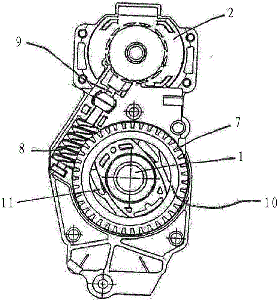
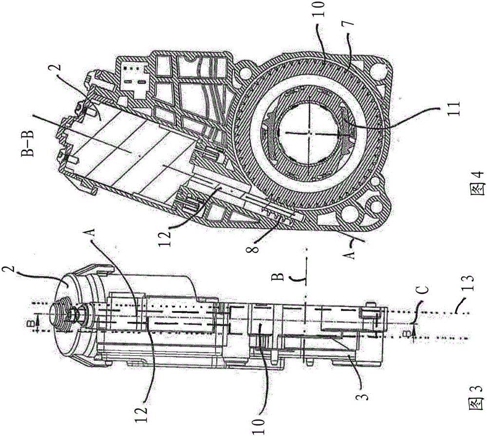
[0020] in figure 2 The reversible seat belt tensioner is shown from the side of the drive device, but there is no cover plate 6. A transmission shaft 9 can be seen between the belt shaft 1 and the motor 2, and the transmission shaft is meshed into the teeth 7 of the drive gear 10 via a worm 8. The connection between the motor 2 and the transmission shaft 9 is here realized by a crown gear transmission, not shown. The driving gear 10 is also connected to the belt shaft 1 via a c...


PUM


Abstract

The invention relates to a reversible belt tightener comprising: - an electric motor (2); - a belt shaft (1) onto which a safety belt can be wound; - a driving wheel (10) that is coaxial to the belt shaft (1); and - a coupling (11) between the belt shaft (1) and the driving wheel (10). The electric motor (2) includes a protruding drive shaft (12) via which the electric motor (2) is connected directly to the driving wheel (10).

Description

Technical field Technical field [0001] The invention relates to a reversible seat belt tensioner. The seat belt tensioner has a motor and a belt shaft that can be driven by the motor through a drive gear along the belt winding direction. Background technique [0002] From WO 2003 / 099619 A2, a reversible seat belt tensioner is known in which the rotational movement of a motor is transmitted to the belt shaft via a drive shaft. The transmission shaft is coupled with the shaft of the motor through a crown gear transmission and is coupled with a drive gear with a shaft through a worm gear transmission. [0003] The disadvantage of this embodiment is that the arrangement of the various components cannot be freely selected, because the gears of the transmission device must respectively deflect the rotational movement by 90 degrees, and therefore the rotation axes of the rotating components in meshing must be at 90 degrees to each other. Angle setting in degrees. In addition, it has b...

Claims


Application Information

Patent Timeline
IPC IPC(8): B60R22/46
CPCB60R22/46B60R2022/4666F16H1/16
Inventor 马蒂亚斯·博格瓦德安德烈亚斯·卢赫特H·卡斯滕森帕特里克·聚尔奥菲利普·林斯安德拉·埃尔斯纳拉尔斯·里肯亚什万斯·辛格
Owner AUTOLIV DEV AB
Why Eureka
Try Eureka